Intel D845EPI Intel Desktop Board D845EPI Product Guide English
Intel D845EPI Manual
 |
View all Intel D845EPI manuals
Add to My Manuals
Save this manual to your list of manuals |
Intel D845EPI manual content summary:
- Intel D845EPI | Intel Desktop Board D845EPI Product Guide English - Page 1
Intel® Desktop Board D845EPI Product Guide Order Number: C46205-001 - Intel D845EPI | Intel Desktop Board D845EPI Product Guide English - Page 2
the instructions, may cause harmful interference to radio communications. However, there is no guarantee that interference will not life sustaining applications. Intel may make changes to specifications and product descriptions at any time, without notice. Desktop Board D845EPI may contain design - Intel D845EPI | Intel Desktop Board D845EPI Product Guide English - Page 3
Product Guide gives information about board layout, component installation, BIOS Setup menus, and regulatory requirements for Intel® Desktop Board D845EPI. Intended Audience The Product Guide is intended for technically qualified personnel. Information Layout The chapters in this Product Guide are - Intel D845EPI | Intel Desktop Board D845EPI Product Guide English - Page 4
Megabyte (1,048,576 bytes) Megabit (1,048,576 bits) Megahertz (one million hertz) Box Contents • Intel desktop board • I/O shield • One IDE cable (ATA66/100) • One diskette drive cable • Quick Reference Guide • Configuration and battery caution statement label • Intel® Express Installer CD-ROM iv - Intel D845EPI | Intel Desktop Board D845EPI Product Guide English - Page 5
1 Desktop Board Features Desktop Board Components 11 Processor ...13 Main Memory ...14 Intel® 845E Chipset ...15 Audio Subsystem ...15 LAN Subsystem (Optional 16 LAN Subsystem Software 16 RJ-45 LAN Connector LEDs 16 Accelerated Graphics Port (AGP 16 Hi-Speed USB 2.0 Support 17 Enhanced - Intel D845EPI | Intel Desktop Board D845EPI Product Guide English - Page 6
USB Configuration Submenu 65 Chipset Configuration Submenu 66 Security Menu ...68 Power Menu ...69 ACPI Submenu...70 Boot Menu...71 Boot Device Priority Submenu 72 Hard Disk Drives Submenu 73 Removable Devices Submenu 74 ATAPI CD-ROM Drives 75 Exit Menu ...76 5 Desktop Board Resources Memory - Intel D845EPI | Intel Desktop Board D845EPI Product Guide English - Page 7
Components 11 2. Location of Standby Power Indicator 19 3. Installing the I/O Shield 24 4. Desktop Board Mounting Screw Holes 25 5. Installing a Processor...26 6. Connecting the Processor Fan Heatsink Cable to the Processor Fan Header 27 7. Installing Memory...28 8. Removing the AGP Card 30 - Intel D845EPI | Intel Desktop Board D845EPI Product Guide English - Page 8
Intel Desktop Board D845EPI Product Guide Tables 1. Feature Summary ...9 2. Desktop Board Components 12 3. Processors Supported by the Desktop Board 13 4. Memory Support ...14 5. RJ-45 LAN Connector LEDs 16 6. Front Panel Audio Header Signal Names (J8A1 34 7. Front Panel Header (J9G1 35 8. USB - Intel D845EPI | Intel Desktop Board D845EPI Product Guide English - Page 9
Features Table 1 describes the major features of Intel® Desktop Board D845EPI. Table 1. Feature Summary Form Factors Processor Memory Chipset Audio LAN (Optional) Graphics I/O Control MicroATX at 9.2 inches by 8.2 inches Support for: • Intel® Pentium® 4 processor in an mPGA-478 socket with a 533 - Intel D845EPI | Intel Desktop Board D845EPI Product Guide English - Page 10
Intel Desktop Board D845EPI Product Guide ✏ NOTE For information about this Intel desktop board, including the Technical Product Specification (TPS), BIOS updates, and device drivers, go to the Intel World Wide Web site at: http://support.intel.com/support/motherboards/desktop Supported Operating - Intel D845EPI | Intel Desktop Board D845EPI Product Guide English - Page 11
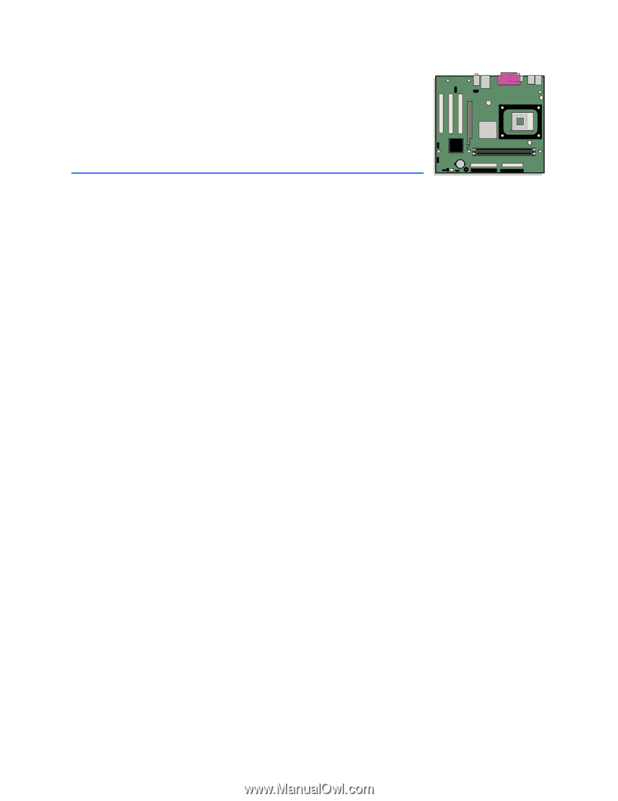
Desktop Board Features Desktop Board Components Figure 1 shows the location of the major components on Desktop Board D845EPI. USB 2.0 Line In AB USB 2.0 C D E U T F S G R QOM P NL K J I H Figure 1. Desktop Board Components OM16286 11 - Intel D845EPI | Intel Desktop Board D845EPI Product Guide English - Page 12
Board D845EPI Product Guide Table 2. Desktop Board Components Item Description A Front panel audio header B CD-in header (ATAPI-style) C 12 V power connector D Rear chassis fan header E Processor socket F Processor fan header G DIMM sockets H Main power connector I Diskette drive - Intel D845EPI | Intel Desktop Board D845EPI Product Guide English - Page 13
needed to provide extra power to the Intel 845E chipset and Intel® processor. Related Links: Go to the following links or pages for more information about: • Supported Intel processors at http://support.intel.com/support/motherboards/desktop • Instructions on installing the processor, see page 26 in - Intel D845EPI | Intel Desktop Board D845EPI Product Guide English - Page 14
Board D845EPI Product Guide Main Memory ✏ NOTE To be fully compliant with all applicable Intel® SDRAM memory specification addendums, the desktop board should be populated with DIMMs that support the Serial Presence Detect (SPD) data structure. If your memory modules do not support SPD, you will - Intel D845EPI | Intel Desktop Board D845EPI Product Guide English - Page 15
) speakers are connected to this output. Related Links: Go to the following link or pages for more information about: • Audio drivers and utilities http://support.intel.com/support/motherboards/desktop • Installing a front panel audio solution, page 34 in Chapter 2 • PCI power management support 15 - Intel D845EPI | Intel Desktop Board D845EPI Product Guide English - Page 16
LAN software and drivers, refer to the D845EPI link on Intel's World Wide Web site at: http://support.intel.com/support/motherboards/desktop RJ-45 LAN Connector LEDs Two LEDs are built into the RJ-45 LAN connector. Table 5 describes the LED states when the desktop board is powered up and the LAN - Intel D845EPI | Intel Desktop Board D845EPI Product Guide English - Page 17
the BIOS reverts all USB 2.0 ports to USB 1.1 operation. This may be required to accommodate operating systems that do not support USB 2.0. Enhanced IDE Interface The ICH4's IDE interface handles the exchange of information between the processor and peripheral devices like hard disks, CD-ROM drives - Intel D845EPI | Intel Desktop Board D845EPI Product Guide English - Page 18
Intel Desktop Board D845EPI Product Guide IDE Auto Configuration If you install an IDE device (such as a hard drive) in your computer, the IDE auto-configuration utility in the BIOS automatically detects and configures the device for your computer. You do not need to run the BIOS Setup program after - Intel D845EPI | Intel Desktop Board D845EPI Product Guide English - Page 19
11 on page 36 for the location of the power connectors. Fan Headers The desktop board has two chassis fan headers and one processor fan header. See Figure 11 on page 36 for the location of the fan headers. Chassis Intrusion The board supports a chassis security feature that detects if the chassis - Intel D845EPI | Intel Desktop Board D845EPI Product Guide English - Page 20
standby current requirements for the desktop board, navigate to the Technical Product Specification by selecting the desktop board from the link below and then selecting Product Documents: http://support.intel.com/support/motherboards/desktop Wake from USB USB bus activity wakes the computer from - Intel D845EPI | Intel Desktop Board D845EPI Product Guide English - Page 21
the desktop board • Install and remove a processor • Install and remove memory • Connect the IDE cable • Instal and remove an AGP card • Connect internal headers • Connect hardware control and power cables • Connect add-in card and peripheral interface connectors • Set the BIOS configuration jumper - Intel D845EPI | Intel Desktop Board D845EPI Product Guide English - Page 22
Intel Desktop Board D845EPI Product Guide Follow these processors, voltage regulators, and heat sinks) • Damage to wires that could cause a short circuit Observe all warnings and cautions that instruct you to refer computer servicing to qualified technical personnel. Installation Instructions - Intel D845EPI | Intel Desktop Board D845EPI Product Guide English - Page 23
that the chassis and certain components; such as the power supply, peripheral drives, wiring, and cables; are components certified for the each of the power supplies' output circuits. Place Battery Marking There is insufficient space on this desktop board to provide instructions for replacing and - Intel D845EPI | Intel Desktop Board D845EPI Product Guide English - Page 24
Intel Desktop Board D845EPI Product Guide Related Links: For information about replacing the battery, go to page 42 in this chapter. Use Only for Intended Applications All Intel desktop boards are evaluated as Information Technology Equipment (I.T.E.) for use in personal computers for installation - Intel D845EPI | Intel Desktop Board D845EPI Product Guide English - Page 25
Components Installing and Removing the Desktop Board Refer to your chassis manual for instructions on installing and removing the desktop board. WARNING This procedure should be done only by qualified technical personnel. Disconnect the computer from its power source before performing the procedures - Intel D845EPI | Intel Desktop Board D845EPI Product Guide English - Page 26
Intel Desktop Board D845EPI Product Guide Installing and Removing a Processor Instructions on how to install the processor to the desktop board are given below. Installing a Processor CAUTION Before installing or removing the processor, make sure that AC power has been removed by unplugging the - Intel D845EPI | Intel Desktop Board D845EPI Product Guide English - Page 27
Figure 6). OM16290 Figure 6. Connecting the Processor Fan Heatsink Cable to the Processor Fan Header Removing a Processor For instruction on how to remove the processor fan heatsink, refer to the Intel World Wide Web site at: http://support.intel.com/support/processors/pentium4/intnotes478.htm 27 - Intel D845EPI | Intel Desktop Board D845EPI Product Guide English - Page 28
Intel Desktop Board D845EPI Product Guide Installing and Removing Memory CAUTION To be fully compliant with all applicable Intel SDRAM memory specification addendums, the board requires DIMMs that support the Serial Presence Detect (SPD) data structure. You can access the PC Serial Presence Detect - Intel D845EPI | Intel Desktop Board D845EPI Product Guide English - Page 29
Installing and Replacing Desktop Board Components 4. Make sure the clips at either end of the (see inset in Figure 7). 8. Replace the computer's cover and reconnect the AC power cord. Removing DIMMs To remove a memory module, follow these steps: 1. Observe the precautions in "Before You Begin" on - Intel D845EPI | Intel Desktop Board D845EPI Product Guide English - Page 30
Intel Desktop Board D845EPI Product Guide Installing and Removing an AGP Card CAUTION When installing any AGP card in the desktop board, ensure that it is fully seated in the AGP connector before you power on the system. If the card is not fully seated in the AGP connector, an electrical short may - Intel D845EPI | Intel Desktop Board D845EPI Product Guide English - Page 31
and Replacing Desktop Board Components Connecting the IDE Cable The Intel® boxed desktop board package includes an IDE cable. The cable connects two drives to the desktop board. The cable supports both ATA-66 and ATA-100 transfer protocols and is backward compatible with drives using slower IDE - Intel D845EPI | Intel Desktop Board D845EPI Product Guide English - Page 32
Intel Desktop Board D845EPI Product Guide A Figure 9. Connecting the IDE Cable B OM16292 32 - Intel D845EPI | Intel Desktop Board D845EPI Product Guide English - Page 33
Installing and Replacing Desktop Board Components Connecting Internal Headers Figure 10 shows the USB 2.0, power LED, front panel, and audio solution headers. A 1 2 3 4 5 6 7 9 10 J8A1 B J6B1 E 1 2 3 4 5 6 7 8 10 J9F2 C 1 2 3 4 5 6 7 8 9 J9G1 13 J8H3 D Item A B C - Intel D845EPI | Intel Desktop Board D845EPI Product Guide English - Page 34
Intel Desktop Board D845EPI Product Guide Installing a Front Panel Audio Solution Table 6 shows the pin assignments for the front panel audio header. Table 6. Front Panel Audio computer and disconnect the AC power cord. 3. Remove the cover. Remove the front panel audio cable. 4. Install a jumper - Intel D845EPI | Intel Desktop Board D845EPI Product Guide English - Page 35
In/Out Description Hard Drive Activity LED Pin Signal In/Out Description Power LED 1 HD_PWR Out Hard disk LED pull- Power switch 7 FP_RESET# In Reset switch Power 8 Ground Ground Not Connected 9 +5 V Power 10 N/C Not connected Installing a USB 2.0 Solution Before installing a USB - Intel D845EPI | Intel Desktop Board D845EPI Product Guide English - Page 36
Intel Desktop Board D845EPI Product Guide Connecting Hardware Control and Power Cables Figure 11 shows the location of the hardware control headers and power connectors. A 1 2 B J1B1 C J2F1 F J8H1 E J8H2 D 2 1 OM16294 Figure 11. Location of Hardware Control and Power Connectors 36 - Intel D845EPI | Intel Desktop Board D845EPI Product Guide English - Page 37
the respective header on the board (see Figure 11, F). Connecting Power Cables CAUTION Failure to use an ATX12V power supply, or not connecting the 12 V processor core voltage power supply connector to the desktop board may result in damage to the desktop board and/or power supply. Figure 11 shows - Intel D845EPI | Intel Desktop Board D845EPI Product Guide English - Page 38
Intel Desktop Board D845EPI Product Guide Connecting Add-In Card and Peripheral Interface Connectors Figure 12 shows the add-in card and peripheral interface connectors. A BC F E Item A B C Description PCI bus connector 3 - Intel D845EPI | Intel Desktop Board D845EPI Product Guide English - Page 39
Program Modes (J9H2) Jumper Setting 31 Mode Normal (default) (1-2) Description The BIOS uses the current configuration and passwords for booting. 31 Configure (2-3) After the Power-On Self-Test (POST) runs, the BIOS displays the Maintenance Menu. Use this menu to clear passwords. 31 Recovery - Intel D845EPI | Intel Desktop Board D845EPI Product Guide English - Page 40
Intel Desktop Board D845EPI Product Guide Clearing Passwords This procedure assumes that the board is installed in the displays the maintenance menu again. 9. Press to save the current values and exit Setup. 10. Turn off the computer. Disconnect the computer's power cord from the AC power - Intel D845EPI | Intel Desktop Board D845EPI Product Guide English - Page 41
Board Components Back Panel Connectors ✏ NOTE The line out connector, located on the back panel, is designed to power either headphones or amplified speakers only. Poor audio keyboard port USB 2.0 ports Serial port Parallel port RJ-45 (optional) USB 2.0 ports Mic in Audio line out Audio line in - Intel D845EPI | Intel Desktop Board D845EPI Product Guide English - Page 42
Intel Desktop Board D845EPI Product Guide Replacing the Battery A coin-cell battery (CR2032) powers the real-time clock and CMOS memory. When the computer is not plugged into a wall socket, the battery has an estimated life of three years. When the computer is plugged in, the - Intel D845EPI | Intel Desktop Board D845EPI Product Guide English - Page 43
Installing and Replacing Desktop Board Components $99(57,0(172 Esiste il pericolo di un esplosione se la pila non viene sostituita in modo corretto. Utilizzare solo pile uguali o di tipo - Intel D845EPI | Intel Desktop Board D845EPI Product Guide English - Page 44
Intel Desktop Board D845EPI Product Guide $:$6 Risiko letupan wujud jika bateri digantikan dengan jenis yang tidak betul. Bateri sepatutnya dikitar semula jika boleh. Pelupusan bateri terpakai mestilah mematuhi peraturan alam sekitar - Intel D845EPI | Intel Desktop Board D845EPI Product Guide English - Page 45
from the AC power source (wall outlet or power adapter). 3. Remove the computer cover. 4. Locate the battery on the board (see Figure 15). 5. Note the orientation of the "+" and "-" on the battery. 6. With a medium flat-bladed screwdriver, gently pry the battery free from its connector. 7. Install - Intel D845EPI | Intel Desktop Board D845EPI Product Guide English - Page 46
Intel Desktop Board D845EPI Product Guide 46 - Intel D845EPI | Intel Desktop Board D845EPI Product Guide English - Page 47
Update utility: 1. Go to the Intel World Wide Web site: http://support.intel.com/support/motherboards/desktop/ 2. Navigate to the D845EPI page, click "[view] Latest BIOS updates", and select the Express BIOS Update utility file. 3. Download the file to your hard drive. (You can also save this file - Intel D845EPI | Intel Desktop Board D845EPI Product Guide English - Page 48
Intel Desktop Board D845EPI Product Guide You can obtain the BIOS update file through your computer supplier or by navigating to the D845EPI page on the Intel World Wide Web site at: http://support.intel.com/support/motherboards/desktop/ Navigate to the D845EPI page, click "[view] Latest BIOS - Intel D845EPI | Intel Desktop Board D845EPI Product Guide English - Page 49
minutes. 6. Listen to the speaker: • Upon applying power, drive A will begin to show activity. In about a minute, two beeps are heard and drive A activity ceases (temporarily) indicating the successful recovery of the BIOS core. Drive A activity will begin again followed by two more beeps indicating - Intel D845EPI | Intel Desktop Board D845EPI Product Guide English - Page 50
Intel Desktop Board D845EPI Product Guide 50 - Intel D845EPI | Intel Desktop Board D845EPI Product Guide English - Page 51
this section may not show the latest settings. For the latest BIOS settings, refer to the Intel Desktop Board D845EPI Technical Product Specification or the Intel World Wide Web site at: http://support.intel.com/support/motherboards/desktop/ ✏ NOTE For reference purposes, you should write down the - Intel D845EPI | Intel Desktop Board D845EPI Product Guide English - Page 52
for Management Boot Integrity Service (BIS) credentials. CPU Stepping Signature No options Displays processor's Stepping Signature. CPU Microcode Update Revision No options Displays processor's Microcode Update Revision. * For information about the BIS, refer to the Intel Web site at: http - Intel D845EPI | Intel Desktop Board D845EPI Product Guide English - Page 53
Main Menu Maintenance Main Advanced Security Power Boot BIOS Version VA84510A.86A.xxxx.xxx Exit Processor Type Processor Speed System Bus Speed System Memory Speed Intel(R) XXXXXXXXXXX X.XX GHz XXX MHz XXX MHz Cache RAM Total Memory Memory Bank 0 Memory Bank 1 Language System Time System Date - Intel D845EPI | Intel Desktop Board D845EPI Product Guide English - Page 54
Intel Desktop Board D845EPI Product Guide Advanced Menu Maintenance Main Advanced Security Power Boot Exit Setup Warning: Setting items on this screen to incorrect values may cause your system to malfunction! ` PCI Configuration ` Boot Configuration ` Peripheral Configuration ` IDE - Intel D845EPI | Intel Desktop Board D845EPI Product Guide English - Page 55
Using the BIOS Setup Program PCI Configuration Submenu Main Advanced Security Power Boot Exit PCI Configuration PCI Slot 1 IRQ Priority PCI Slot 2 IRQ Priority PCI Slot 3 IRQ Priority [Auto] m o n p Enter F1 P9 F10 ESC Select Screen Select - Intel D845EPI | Intel Desktop Board D845EPI Product Guide English - Page 56
Intel Desktop Board D845EPI Product Guide Boot Configuration Submenu Main Advanced Security Power Boot Exit Boot Configuration Plug & Play O/S Numlock ASF Support [No] [On] [Enabled] m o n p Enter F1 P9 F10 ESC Select Screen Select Item Select ` Sub-Menu General Help Setup Defaults Save and - Intel D845EPI | Intel Desktop Board D845EPI Product Guide English - Page 57
BIOS Setup Program Peripheral Configuration Submenu Main Advanced Security Power Boot Exit Peripheral Configuration Serial Port A Parallel Port Audio LAN Auto assigns the first free COM port, normally COM1, the address 3F8h, and the interrupt IRQ4. An * (asterisk) displayed next to an address - Intel D845EPI | Intel Desktop Board D845EPI Product Guide English - Page 58
Board D845EPI Product Guide Table 17. Peripheral Configuration Submenu (continued) Feature Options Description Mode Base I/O Address (This feature is present only when Parallel Port is set to Enabled) Interrupt (This feature is present only when Parallel Port is set to Enabled) Audio LAN - Intel D845EPI | Intel Desktop Board D845EPI Product Guide English - Page 59
a PCI device to initiate a transaction as a master. Specifies the hard disk drive pre-delay. Causes the BIOS to insert a delay before attempting to detect IDE drives in the system. Reports type of connected IDE device. When selected, displays the Primary IDE Master submenu. Reports type of connected - Intel D845EPI | Intel Desktop Board D845EPI Product Guide English - Page 60
Desktop Board D845EPI Product Guide Primary/Secondary IDE Master/Slave Submenus Main Advanced Security Power Boot Exit ` [ : Xxxxxxxxx ] Type Maximum Capacity [Auto] [Auto] Configuration Options Selected By BIOS LBA Mode : Block Mode : PIO Mode : Ultra DMA : Cable Detected : [Supported - Intel D845EPI | Intel Desktop Board D845EPI Product Guide English - Page 61
Using the BIOS Setup Program Table 19. Primary/Secondary IDE Master/Slave Submenus (continued) Feature Options 4 • Mode 5 None Specifies the PIO mode. Specifies the Ultra DMA mode for the drive. Displays the type of cable connected to the IDE interface: 40-conductor or 80-conductor (for ATA - Intel D845EPI | Intel Desktop Board D845EPI Product Guide English - Page 62
Intel Desktop Board D845EPI Product Guide Diskette Configuration Submenu Main Advanced Security Diskette Configuration Power Boot Diskette Controller [Enabled] in Table 20 is used to configure the diskette drive. Table 20. Diskette Configuration Submenu Feature Options Description - Intel D845EPI | Intel Desktop Board D845EPI Product Guide English - Page 63
Using the BIOS Setup Program Event Log Configuration Submenu Main Advanced Security Event Log Configuration Power Boot Exit Event Log [Space Available] View Event Log Clear Event Log Event Logging Mark Events As Read [Enabled] m o n p Enter F1 P9 F10 ESC Select - Intel D845EPI | Intel Desktop Board D845EPI Product Guide English - Page 64
Intel Desktop Board D845EPI Product Guide Video Configuration Submenu Main Advanced Security Video Configuration Power Boot Exit AGP Aperture Size Primary Video Adapter [ 64MB] [AGP] m o n p Enter F1 P9 F10 ESC Select Screen Select Item Select ` Sub-Menu General Help Setup Defaults Save - Intel D845EPI | Intel Desktop Board D845EPI Product Guide English - Page 65
Using the BIOS Setup Program USB Configuration Submenu Main Advanced Security Power USB Configuration High-Speed USB [Enabled] Legacy USB Support USB 2.0 Legacy Support [Enabled] [FullSpeed] Boot Exit m o n p Enter F1 P9 F10 ESC Select Screen Select Item Select ` Sub-Menu General Help - Intel D845EPI | Intel Desktop Board D845EPI Product Guide English - Page 66
Intel Desktop Board D845EPI Product Guide Chipset Configuration Submenu Main Advanced Security Chipset Configuration Power Boot Setup Warning: Setting items on this screen to incorrect values may cause your system to malfunction! ISA Enable Bit PCI Latency Timer [Enabled] [32] - Intel D845EPI | Intel Desktop Board D845EPI Product Guide English - Page 67
Using the BIOS Setup Program Table 24. Chipset Configuration Submenu (continued) Feature Options Description SDRAM Timing Control • Auto (default) • Manual - Aggressive • Manual - User Defined Auto allows timings to be programmed according to the memory detected. Manual - Aggressive selects - Intel D845EPI | Intel Desktop Board D845EPI Product Guide English - Page 68
Intel Desktop Board D845EPI Product Guide Security Menu Main Advanced Security Power Boot Exit Supervisor Password : User Password the user password. User access Level (Note 2) • Limited • No access Sets BIOS Setup Utility access rights for user level. • View Only • Full (default) Notes - Intel D845EPI | Intel Desktop Board D845EPI Product Guide English - Page 69
the BIOS Setup Program Power Menu Main Advanced Security Power Boot ACPI After Power Failure displays the ACPI submenu. After Power Failure • Stay Off • Last State (default) • Power On Determines the mode of operation if a power loss occurs. Stay Off keeps the power off until the power - Intel D845EPI | Intel Desktop Board D845EPI Product Guide English - Page 70
Intel Desktop Board D845EPI Product Guide ACPI Submenu Main Advanced Security Power Boot Advanced Configuration and Power Interface Exit ACPI Suspend State Wake on LAN from S5 [S1 State] [Stay Off] S1 is the safest mode but consumes more power. S3 consumes low power but drivers may not support - Intel D845EPI | Intel Desktop Board D845EPI Product Guide English - Page 71
normal POST messages. • Enabled (default) Enabled displays OEM logo instead of POST messages. Intel Rapid BIOS Boot Scan User Flash Area PXE Boot to LAN USB Boot Boot Device Priority Hard Disk Drives Removable Devices ATAPI CD-ROM Drives • Disabled Allows BIOS to skip certain tests while booting - Intel D845EPI | Intel Desktop Board D845EPI Product Guide English - Page 72
Intel Desktop Board D845EPI Product Guide Boot Device Priority Submenu Main Advanced Security Power Boot Exit 1st Boot Device 2nd Boot Device 3rd Boot Device [1st FLOPPY DRIVE] [xxxxxxxxxxx] [xxxxxxxxxxx] Specifies the boot sequence from the available devices. A device enclosed in parenthesis - Intel D845EPI | Intel Desktop Board D845EPI Product Guide English - Page 73
Using the BIOS Setup Program Hard Disk Drives Submenu Main Advanced Security Power Boot Exit 1st Drive 2nd Drive 3rd Drive 4th Drive [xxxxxxxxxxxxx] [ this type is installed. This list will display up to twelve hard disk drives, the maximum number of hard disk drives supported by the BIOS. 73 - Intel D845EPI | Intel Desktop Board D845EPI Product Guide English - Page 74
Intel Desktop Board D845EPI Product Guide Removable Devices Submenu Main Advanced Security Power Boot Exit 1st Drive [1st FLOPPY DRIVE] Specifies the boot sequence installed. This list will display up to four removable devices, the maximum number of removable devices supported by the BIOS. 74 - Intel D845EPI | Intel Desktop Board D845EPI Product Guide English - Page 75
Using the BIOS Setup Program ATAPI CD-ROM Drives Main Advanced Security Power Boot Exit 1st Drive 2nd Drive [xxxxxxx] [xxxxxxx] Specifies the boot this type is installed. This list will display up to four ATAPI CD-ROM drives, the maximum number of ATAPI CD-ROM drives supported by the BIOS. 75 - Intel D845EPI | Intel Desktop Board D845EPI Product Guide English - Page 76
Intel Desktop Board D845EPI Product Guide Exit Menu Main Advanced Security Power Boot Exit Exit Saving Changes Exit Discarding Changes Load BIOS reads the Setup values from flash memory. If this memory is corrupted, the BIOS reads the custom defaults. If no custom defaults are set, the BIOS reads - Intel D845EPI | Intel Desktop Board D845EPI Product Guide English - Page 77
KB Description Extended Memory Runtime BIOS Reserved Available high DOS memory (open to the PCI bus) Video memory and BIOS Extended BIOS data (movable by memory manager software) Extended conventional memory Conventional memory System Resource Open Parallel port Diskette drive Parallel port (for - Intel D845EPI | Intel Desktop Board D845EPI Product Guide English - Page 78
Desktop Board D845EPI Product Guide Interrupts Table 36. Interrupts IRQ System Resource NMI I/O channel check 0 Reserved, interval timer 1 Reserved, keyboard buffer full 2 Reserved, cascade interrupt from slave PIC 3 COM2* 4 COM1* 5 LPT2 (Plug & Play option) / ** 6 Diskette drive - Intel D845EPI | Intel Desktop Board D845EPI Product Guide English - Page 79
Desktop Board D845EPI reports POST errors in two ways: • By sounding a beep code • By displaying an error message on the monitor BIOS Beep Codes The BIOS beep codes are listed in Table 37. The BIOS also issues a beep code (one long tone followed by two short tones) during POST if the video - Intel D845EPI | Intel Desktop Board D845EPI Product Guide English - Page 80
Intel Desktop Board D845EPI Product Guide BIOS Error Messages When a recoverable error occurs during the POST, the BIOS displays an error message describing the problem. Table 38. BIOS Error Messages Error Message Explanation GA20 Error An error occurred with Gate-A20 when switching to - Intel D845EPI | Intel Desktop Board D845EPI Product Guide English - Page 81
. BIOS Error Messages (continued) Error Message Explanation Memory Size Decreased Memory size has decreased since the last boot. If no memory was removed, then memory may be bad. Memory Size Increased Memory size has increased since the last boot. If no memory was added, there may be a problem - Intel D845EPI | Intel Desktop Board D845EPI Product Guide English - Page 82
Intel Desktop Board D845EPI Product Guide 82 - Intel D845EPI | Intel Desktop Board D845EPI Product Guide English - Page 83
including Electrical Business Equipment. (International) European Union Declaration of Conformity Statement We, Intel Corporation, declare under our sole responsibility that the product Intel® Desktop Board D845EPI is in conformity with all applicable essential requirements necessary for CE marking - Intel D845EPI | Intel Desktop Board D845EPI Product Guide English - Page 84
Intel Desktop Board D845EPI Product Guide 7fy„vÁDette produkt er i overensstemmelse med det europæiske direktiv 89/336/EEC & 73/23/EEC. 7†…hsÁDit product is in navolging van de bepalingen - Intel D845EPI | Intel Desktop Board D845EPI Product Guide English - Page 85
Regulatory Compliance EMC Regulations Desktop Board D845EPI complies with the EMC regulations stated in Table 40 when correctly installed in a compatible host system. Table 40. EMC Regulations Regulation Title FCC Class B Title - Intel D845EPI | Intel Desktop Board D845EPI Product Guide English - Page 86
D845EPI Product Guide Product Certification Markings (Board Level) Desktop Board D845EPI has the following product certification markings: Table 41. Product Certification Markings Description UL joint US/Canada Recognized Component mark. Includes adjacent UL file number for Intel desktop boards
-
 1
1 -
 2
2 -
 3
3 -
 4
4 -
 5
5 -
 6
6 -
 7
7 -
8
-
9
-
10
-
11
-
12
-
13
-
14
-
15
-
16
-
17
-
18
-
19
-
20
-
21
-
22
-
23
-
24
-
25
-
26
-
27
-
28
-
29
-
30
-
31
-
32
-
33
-
34
-
35
-
36
-
37
-
38
-
39
-
40
-
41
-
42
-
43
-
44
-
45
-
46
-
47
-
48
-
49
-
50
-
51
-
52
-
53
-
54
-
55
-
56
-
57
-
58
-
59
-
60
-
61
-
62
-
63
-
64
-
65
-
66
-
67
-
68
-
69
-
70
-
71
-
72
-
73
-
74
-
75
-
76
-
77
-
78
-
79
-
80
-
81
-
82
-
83
-
84
-
85
-
86
 |
 |
Intel
®
Desktop Board
D845EPI Product Guide
Order Number:
C46205-001