Intel D845EPI Intel Desktop Board D845EPI Product Guide English - Page 7

Connecting the Processor Fan Heatsink Cable to the Processor Fan Header

Page 7 highlights

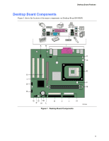
Contents B Regulatory Compliance Safety Regulations ...83 European Union Declaration of Conformity Statement 83 Product Ecology Statements 84 EMC Regulations ...85 Product Certification Markings (Board Level 86 Figures 1. Desktop Board Components 11 2. Location of Standby Power Indicator 19 3. Installing the I/O Shield 24 4. Desktop Board Mounting Screw Holes 25 5. Installing a Processor...26 6. Connecting the Processor Fan Heatsink Cable to the Processor Fan Header 27 7. Installing Memory...28 8. Removing the AGP Card 30 9. Connecting the IDE Cable 32 10. Internal Headers ...33 11. Location of Hardware Control and Power Connectors 36 12. Add-in Card and Peripheral Interface Connectors 38 13. Location of the BIOS Configuration Jumper Block 39 14. Back Panel Connectors 41 15. Removing the Battery from the Desktop Board 46 vii

  • 1
  • 2
  • 3
  • 4
  • 5
  • 6
  • 7
  • 8
  • 9
  • 10
  • 11
  • 12
  • 13
  • 14
  • 15
  • 16
  • 17
  • 18
  • 19
  • 20
  • 21
  • 22
  • 23
  • 24
  • 25
  • 26
  • 27
  • 28
  • 29
  • 30
  • 31
  • 32
  • 33
  • 34
  • 35
  • 36
  • 37
  • 38
  • 39
  • 40
  • 41
  • 42
  • 43
  • 44
  • 45
  • 46
  • 47
  • 48
  • 49
  • 50
  • 51
  • 52
  • 53
  • 54
  • 55
  • 56
  • 57
  • 58
  • 59
  • 60
  • 61
  • 62
  • 63
  • 64
  • 65
  • 66
  • 67
  • 68
  • 69
  • 70
  • 71
  • 72
  • 73
  • 74
  • 75
  • 76
  • 77
  • 78
  • 79
  • 80
  • 81
  • 82
  • 83
  • 84
  • 85
  • 86

Contents
vii
B
Regulatory Compliance
Safety Regulations
..............................................................................................................
83
European Union Declaration of Conformity Statement
........................................................
83
Product Ecology Statements
...............................................................................................
84
EMC Regulations
................................................................................................................
85
Product Certification Markings (Board Level)
......................................................................
86
Figures
1. Desktop Board Components
.........................................................................................
11
2.
Location of Standby Power Indicator
.............................................................................
19
3.
Installing the I/O Shield
.................................................................................................
24
4.
Desktop Board Mounting Screw Holes
..........................................................................
25
5. Installing a Processor
....................................................................................................
26
6.
Connecting the Processor Fan Heatsink Cable to the Processor Fan Header
..............
27
7. Installing Memory
..........................................................................................................
28
8.
Removing the AGP Card
..............................................................................................
30
9.
Connecting the IDE Cable
.............................................................................................
32
10. Internal Headers
...........................................................................................................
33
11. Location of Hardware Control and Power Connectors
..................................................
36
12. Add-in Card and Peripheral Interface Connectors
.........................................................
38
13. Location of the BIOS Configuration Jumper Block
........................................................
39
14. Back Panel Connectors
................................................................................................
41
15. Removing the Battery from the Desktop Board
.............................................................
46