Intel D845GLVA Product Specification - Page 32
LAN Subsystem Optional - lan driver
 |
View all Intel D845GLVA manuals
Add to My Manuals
Save this manual to your list of manuals |
Page 32 highlights
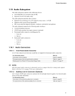
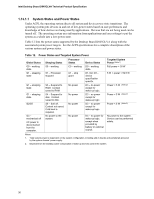
Intel Desktop Board D845GLVA Technical Product Specification 1.10.1.3 ATAPI CD-ROM Audio Connector A 1 x 4-pin ATAPI-style connector connects an internal ATAPI CD-ROM drive to the audio mixer. For information about The location of the ATAPI CD-ROM connector The signal names of the ATAPI CD-ROM connector Refer to Figure 5, page 50 Table 23, page 51 1.10.2 Audio Subsystem Software Audio software and drivers are available from Intel's World Wide Web site. For information about Obtaining audio software and drivers Refer to Section 1.3, page 16 1.11 LAN Subsystem (Optional) The Network Interface Controller subsystem consists of the ICH4 (with integrated LAN Media Access Controller) and a physical layer interface device. Features of the LAN subsystem include: • PCI Bus Master interface • CSMA/CD Protocol Engine • Serial CSMA/CD unit interface that supports the 82562ET (10/100 Mbit/sec Ethernet) • PCI Power Management Supports ACPI technology Supports LAN wake capabilities 1.11.1 Intel® 82562ET Platform LAN Connect Device The Intel 82562ET component provides an interface to the back panel RJ-45 connector with integrated LEDs. The Intel 82562ET provides the following functions: • Basic 10/100 Ethernet LAN connectivity • Supports RJ-45 connector with status indicator LEDs on the back panel • Full device driver compatibility • ACPI support • Programmable transit threshold • Configuration EEPROM that contains the MAC address 1.11.2 RJ-45 LAN Connector with Integrated LEDs Two LEDs are built into the RJ-45 LAN connector. Table 10 describes the LED states when the Desktop Board is powered up and the LAN subsystem is operating. 32
-
 1
1 -
2
-
3
-
4
-
5
-
6
-
7
-
8
-
9
-
10
-
11
-
12
-
13
-
14
-
15
-
16
-
17
-
18
-
19
-
20
-
21
-
22
-
23
-
24
-
25
-
26
-
 27
27 -
 28
28 -
 29
29 -
 30
30 -
 31
31 -
 32
32 -
 33
33 -
 34
34 -
 35
35 -
 36
36 -
 37
37 -
38
-
39
-
40
-
41
-
42
-
43
-
44
-
45
-
46
-
47
-
48
-
49
-
50
-
51
-
52
-
53
-
54
-
55
-
56
-
57
-
58
-
59
-
60
-
61
-
62
-
63
-
64
-
65
-
66
-
67
-
68
-
69
-
70
-
71
-
72
-
73
-
74
-
75
-
76
-
77
-
78
-
79
-
80
-
81
-
82
-
83
-
84
-
85
-
86
-
87
-
88
-
89
-
90
-
91
-
92
-
93
-
94
-
95
-
96
-
97
-
98
-
99
-
100
-
101
-
102
-
103
-
104
-
105
-
106
-
107
-
108
-
109
-
110
-
111
-
112
-
113
-
114
 |
 |
