Intel D845GLVA Product Specification - Page 55
Front Panel Connector
 |
View all Intel D845GLVA manuals
Add to My Manuals
Save this manual to your list of manuals |
Page 55 highlights
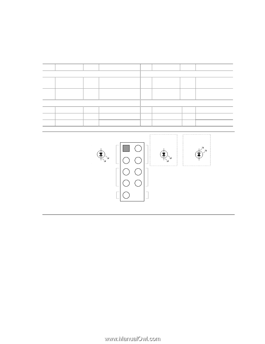
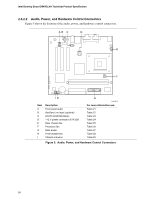
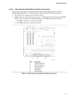
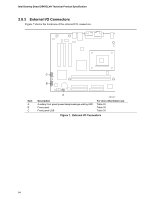
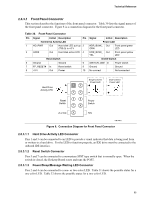
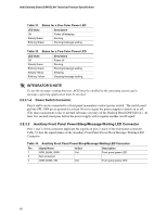
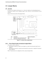
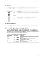
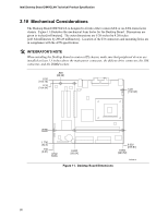
Technical Reference 2.8.3.1 Front Panel Connector This section describes the functions of the front panel connector. Table 30 lists the signal names of the front panel connector. Figure 8 is a connection diagram for the front panel connector. Table 30. Front Panel Connector Pin Signal In/Out Description Pin Hard Drive Activity LED 1 HD_PWR Out Hard disk LED pull-up 2 (750 Ω) to +5 V 3 HAD# Out Hard disk active LED 4 Reset Switch 5 Ground Ground 6 7 FP_RESET# In Reset switch 8 9 +5 V Out Power 10 Signal In/Out Description Power LED HDR_BLNK_ Out GRN Front panel green LED HDR_BLNK_ Out YEL Front panel yellow LED On/Off Switch SWITCH_ON# In Power switch Ground Ground No connect Not connected Hard Drive Activity LED + − Reset Switch 12 34 56 78 +5 V DC 9 Single-colored Power LED + − Dual-colored Power LED − + Power Switch N/C OM15964 Figure 8. Connection Diagram for Front Panel Connector 2.8.3.1.1 Hard Drive Activity LED Connector Pins 1 and 3 can be connected to an LED to provide a visual indicator that data is being read from or written to a hard drive. For the LED to function properly, an IDE drive must be connected to the onboard IDE interface. 2.8.3.1.2 Reset Switch Connector Pins 5 and 7 can be connected to a momentary SPST type switch that is normally open. When the switch is closed, the Desktop Board resets and runs the POST. 2.8.3.1.3 Power/Sleep/Message Waiting LED Connector Pins 2 and 4 can be connected to a one- or two-color LED. Table 31 shows the possible states for a one-color LED. Table 32 shows the possible states for a two-color LED. 55
-
 1
1 -
2
-
3
-
4
-
5
-
6
-
7
-
8
-
9
-
10
-
11
-
12
-
13
-
14
-
15
-
16
-
17
-
18
-
19
-
20
-
21
-
22
-
23
-
24
-
25
-
26
-
27
-
28
-
29
-
30
-
31
-
32
-
33
-
34
-
35
-
36
-
37
-
38
-
39
-
40
-
41
-
42
-
43
-
44
-
45
-
46
-
47
-
48
-
49
-
 50
50 -
 51
51 -
 52
52 -
 53
53 -
 54
54 -
 55
55 -
 56
56 -
 57
57 -
 58
58 -
 59
59 -
 60
60 -
61
-
62
-
63
-
64
-
65
-
66
-
67
-
68
-
69
-
70
-
71
-
72
-
73
-
74
-
75
-
76
-
77
-
78
-
79
-
80
-
81
-
82
-
83
-
84
-
85
-
86
-
87
-
88
-
89
-
90
-
91
-
92
-
93
-
94
-
95
-
96
-
97
-
98
-
99
-
100
-
101
-
102
-
103
-
104
-
105
-
106
-
107
-
108
-
109
-
110
-
111
-
112
-
113
-
114
 |
 |