Intel D845PT Product Specification - Page 27
USB 1.1 Support - front panel connections
 |
View all Intel D845PT manuals
Add to My Manuals
Save this manual to your list of manuals |
Page 27 highlights
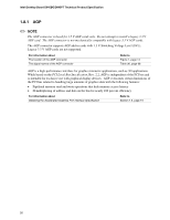
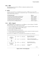
Product Description 1.8.2 USB The following sections describe the USB port configurations implemented on the D845BG/D845PT boards. ✏ NOTE Computer systems that have an unshielded cable attached to a USB port may not meet FCC Class B requirements, even if no device is attached to the cable. Use shielded cable that meets the requirements for full-speed devices. For information about The location of the USB connectors on the back panel The signal names of the back panel USB connectors The location of the front panel USB connector The signal names of the front panel USB connector The front panel, UHCI, and USB specifications Refer to Figure 11, page 55 Table 19, page 56 Figure 16, page 71 Table 42, page 72 Section 1.5, page 19 1.8.2.1 USB 1.1 Support The D845BG/D845PT boards support up to seven USB ports, as shown in Figure 6. The ICH2 provides four ports, three of which are user-accessible: • Two ports implemented with stacked back panel connectors, adjacent to the PS/2 connectors • One port accessible through an optional CNR connector • One port routed to the SMSC USB hub The onboard SMSC USB hub provides four ports: • Two ports implemented with stacked back panel connectors, adjacent to the audio connectors • Two ports routed to the front panel USB connector For more than seven USB devices, an external hub can be connected to any of the ports. 82801BA I/O Controller Hub (ICH2) USB SMSC LPC47M142 LPC Bus I/O Controller USB USB USB ports (2) CNR connector Back panel USB connectors adjacent to the PS/2 ports USB port accesible through a USB connector on an optional CNR add-in card USB USB ports (2) Back panel USB connectors adjacent to the audio connectors USB USB ports (2) Front panel USB connectors Figure 6. USB 1.1 Port Configuration OM12339 27
-
 1
1 -
2
-
3
-
4
-
5
-
6
-
7
-
8
-
9
-
10
-
11
-
12
-
13
-
14
-
15
-
16
-
17
-
18
-
19
-
20
-
21
-
 22
22 -
 23
23 -
 24
24 -
 25
25 -
 26
26 -
 27
27 -
 28
28 -
 29
29 -
 30
30 -
 31
31 -
 32
32 -
33
-
34
-
35
-
36
-
37
-
38
-
39
-
40
-
41
-
42
-
43
-
44
-
45
-
46
-
47
-
48
-
49
-
50
-
51
-
52
-
53
-
54
-
55
-
56
-
57
-
58
-
59
-
60
-
61
-
62
-
63
-
64
-
65
-
66
-
67
-
68
-
69
-
70
-
71
-
72
-
73
-
74
-
75
-
76
-
77
-
78
-
79
-
80
-
81
-
82
-
83
-
84
-
85
-
86
-
87
-
88
-
89
-
90
-
91
-
92
-
93
-
94
-
95
-
96
-
97
-
98
-
99
-
100
-
101
-
102
-
103
-
104
-
105
-
106
-
107
-
108
-
109
-
110
-
111
-
112
-
113
-
114
-
115
-
116
-
117
-
118
-
119
-
120
-
121
-
122
-
123
-
124
-
125
-
126
-
127
-
128
-
129
-
130
 |
 |
