Intel D865GSA Intel Desktop Board D865GSA Product Guide English - Page 16
LAN Subsystem - motherboard driver
 |
View all Intel D865GSA manuals
Add to My Manuals
Save this manual to your list of manuals |
Page 16 highlights
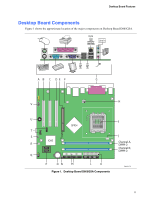
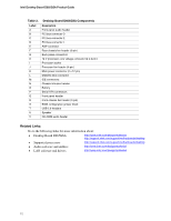
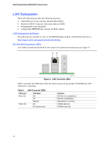
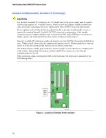
Intel Desktop Board D865GSA Product Guide LAN Subsystem The LAN subsystem provides the following functions: • 10/100 Ethernet LAN controller (Realtek RTL8100C) • Support for RJ-45 connector with status indicator LEDs • Programmable transit threshold • Configurable EEPROM that contains the MAC address LAN Subsystem Software For LAN software and drivers, refer to the D865GSA link on Intel's World Wide Web site at: http://support.intel.com/support/motherboards/desktop RJ-45 LAN Connector LEDs Two LEDs are built into the RJ-45 LAN connector located on the back panel (see Figure 2). AB OM19171 Figure 2. LAN Connector LEDs Table 5 describes the LED states when the board is powered up and the 10/100 Ethernet LAN subsystem is operating. Table 5. LAN Connector LEDs LED Color Green (A) Yellow (B) LED State Off On Blinking Off On (steady state) Indicates LAN link is not established LAN link is established LAN activity is occurring 10 Mb/s data rate 100 Mb/s data rate 16
-
 1
1 -
2
-
3
-
4
-
5
-
6
-
7
-
8
-
9
-
10
-
 11
11 -
 12
12 -
 13
13 -
 14
14 -
 15
15 -
 16
16 -
 17
17 -
 18
18 -
 19
19 -
 20
20 -
 21
21 -
22
-
23
-
24
-
25
-
26
-
27
-
28
-
29
-
30
-
31
-
32
-
33
-
34
-
35
-
36
-
37
-
38
-
39
-
40
-
41
-
42
-
43
-
44
-
45
-
46
-
47
-
48
-
49
-
50
-
51
-
52
-
53
-
54
-
55
-
56
-
57
-
58
-
59
-
60
-
61
-
62
-
63
-
64
 |
 |
