Contents
vii
Figures
1.
Desktop Board D865GSA Components
.........................................................................
11
2.
LAN Connector LEDs
.....................................................................................................
16
3.
Location of Standby Power Indicator
..............................................................................
20
4.
Installing the I/O Shield
...................................................................................................
25
5.
Desktop Board D865GSA Mounting Screw Hole Locations
...........................................
26
6.
Lift the Socket Lever
.......................................................................................................
27
7.
Lift the Load Plate
...........................................................................................................
27
8.
Remove the Protective Socket Cover
.............................................................................
28
9.
Remove the Processor from the Protective Processor Cover
........................................
28
10. Install the Processor
.......................................................................................................
29
11. Close the Load Plate
......................................................................................................
29
12. Connecting the Processor Fan Heat Sink Cable to the Processor Fan Header
.............
30
13. Dual Channel Memory Configuration Example
..............................................................
31
14. Use DDR DIMMs
............................................................................................................
32
15. Installing a DIMM
............................................................................................................
33
16. Installing an AGP Card
...................................................................................................
35
17. Removing an AGP Card
.................................................................................................
36
18. Connecting the IDE Cable
..............................................................................................
37
19. Connecting the Serial ATA Cable
...................................................................................
38
20. Internal Headers
.............................................................................................................
39
21. Location of Chassis Fan Headers
..................................................................................
42
22. Connecting Power Supply Cables
..................................................................................
43
23. Location of Other Connectors
.........................................................................................
44
24. Location of the BIOS Configuration Jumper Block
.........................................................
45
25. Back Panel Connectors
..................................................................................................
47
26. Removing the Battery
.....................................................................................................
52
Tables
1.
Feature Summary
.............................................................................................................
9
2.
Desktop Board D865GSA Components
.........................................................................
12
3.
Power Supply Requirements
..........................................................................................
13
4.
Desktop Board D865GSA Memory Speeds
...................................................................
14
5.
LAN Connector LEDs
.....................................................................................................
16
6.
Audio Header Signal Names
..........................................................................................
40
7.
CD-ROM Audio Header Signal Names
..........................................................................
40
8.
USB 2.0 Header Signal Names
......................................................................................
41
9.
Front Panel Header Signal Names
.................................................................................
41
10.
Jumper Settings for the BIOS Setup Program Modes
....................................................
46
11.
Beep Codes
....................................................................................................................
55
12.
BIOS Error Messages
.....................................................................................................
55
13.
Safety Regulations
.........................................................................................................
57
14.
Lead-Free Board Markings
.............................................................................................
61
15.
EMC Regulations
............................................................................................................
62
16.
Product Certification Markings
........................................................................................
63

 1
1 2
2 3
3 4
4 5
5 6
6 7
7 8
8 9
9 10
10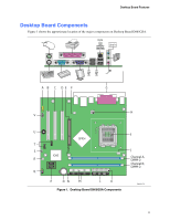 11
11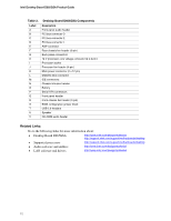 12
12

