Intel D865GVHZ Product Guide - Page 34
Connecting the Front Panel Header, Connecting the USB 2.0 Header, Table 5., Front Panel Header
 |
UPC - 675900599772
View all Intel D865GVHZ manuals
Add to My Manuals
Save this manual to your list of manuals |
Page 34 highlights
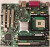
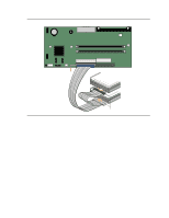
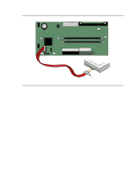
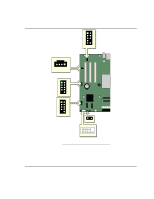
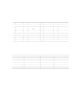
Intel Desktop Board D865GVHZ Product Guide Connecting the Front Panel Header Before connecting the front panel header, observe the precautions in "Before You Begin" on page 21. Figure 9-C on page 33 shows the location of the front panel header. Table 5 shows the pin assignments for the front panel header. Table 5. Front Panel Header Pin Signal In/Out Description Hard Drive Activity LED Pin Signal In/Out Description Power LED 1 HD_PWR 3 HDA# Out Hard disk LED pull- 2 HDR_BLNK_GRN Out Front panel green up (330 ) to +5 V LED Out Hard disk active LED 4 HDR_BLNK_YEL Out Front panel yellow LED Reset Switch On/Off Switch 5 Ground 7 FP_RESET# In 9 +5 V Out Ground Reset switch Power 6 SWITCH_ON# In 8 Ground 10 N/C Power switch Ground Not connected Connecting the USB 2.0 Header Before connecting the USB 2.0 header, observe the precautions in "Before You Begin" on page 21. Figure 9-D and E on page 33 shows the location of the USB 2.0 header. Table 6 shows the pin assignments for the header. Table 6. USB 2.0 Header USB Port A Pin Signal Name Pin 1 Power 2 3 D- 4 5 D+ 6 7 Ground 8 9 Key (no pin) 10 Note: USB ports may be assigned as needed. USB Port B Signal Name Power DD+ Ground Not connected 34
-
 1
1 -
2
-
3
-
4
-
5
-
6
-
7
-
8
-
9
-
10
-
11
-
12
-
13
-
14
-
15
-
16
-
17
-
18
-
19
-
20
-
21
-
22
-
23
-
24
-
25
-
26
-
27
-
28
-
 29
29 -
 30
30 -
 31
31 -
 32
32 -
 33
33 -
 34
34 -
 35
35 -
 36
36 -
 37
37 -
 38
38 -
 39
39 -
40
-
41
-
42
-
43
-
44
-
45
-
46
-
47
-
48
-
49
-
50
-
51
-
52
-
53
-
54
-
55
-
56
-
57
-
58
-
59
-
60
-
61
-
62
-
63
-
64
-
65
-
66
-
67
-
68
-
69
-
70
-
71
-
72
-
73
-
74
-
75
-
76
-
77
-
78
-
79
-
80
-
81
-
82
-
83
-
84
-
85
-
86
-
87
-
88
 |
 |
