Contents
vii
Boot Menu
...........................................................................................................................
72
Boot Device Priority Submenu
....................................................................................
73
Hard Disk Drives Submenu
........................................................................................
74
Removable Devices Submenu
...................................................................................
75
ATAPI CD-ROM Drives
..............................................................................................
76
Exit Menu
............................................................................................................................
77
5
Desktop Board Resources
Memory Map
.......................................................................................................................
79
DMA Channels
....................................................................................................................
79
Interrupts
.............................................................................................................................
80
A
Error Messages and Indicators
BIOS Beep Codes
...............................................................................................................
81
BIOS Error Messages
.........................................................................................................
82
B
Regulatory Compliance
Safety Regulations
..............................................................................................................
85
European Union Declaration of Conformity Statement
........................................................
85
Product Ecology Statements
...............................................................................................
86
EMC Regulations
................................................................................................................
87
Product Certification Markings (Board Level)
......................................................................
88
Figures
1.
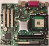
Desktop Board D865GVHZ Components
......................................................................
11
2.
Installing the I/O Shield
.................................................................................................
24
3.
Location of Mounting Screw Holes
................................................................................
25
4.
Installing a Processor
....................................................................................................
26
5.
Connecting the Processor Fan Heat Sink Cable to the Processor Fan Connector
........
27
6.
Installing a Memory Module
..........................................................................................
28
7.
Connecting the IDE Cable
............................................................................................
31
8.
Connecting the Serial ATA Cable
.................................................................................
32
9.
Internal Headers
...........................................................................................................
33
10.
Location of Hardware Control Headers and Power Connectors
....................................
36
11.
PCI Bus Add-in Card and Peripheral Interface Connectors
...........................................
38
12.
Location of the BIOS Configuration Jumper Block
........................................................
39
13.
Back Panel Connectors
................................................................................................
41
14.
Removing the Battery
...................................................................................................
45
Tables
1.
Feature Summary
...........................................................................................................
9
2.
Desktop Board Components
.........................................................................................
12
3.
Supported Processors
..................................................................................................
13
4.
RJ-45 10/100 Ethernet LAN Connector LEDs
...............................................................
16
5.
Front Panel Header
......................................................................................................
34
6.
USB 2.0 Header
............................................................................................................
34
7.
Front Panel Audio Header Signal Names
......................................................................
35
8.
Jumper Settings for the BIOS Setup Program Modes
...................................................
39
9.
BIOS Setup Program Menu Bar
....................................................................................
51
 1
1 2
2 3
3 4
4 5
5 6
6 7
7 8
8 9
9 10
10 11
11 12
12

