Intel D945GCPE Product Guide - Page 41
Connecting to the Serial Port Header, Connecting to the Chassis Intrusion Header
 |
UPC - 735858195195
View all Intel D945GCPE manuals
Add to My Manuals
Save this manual to your list of manuals |
Page 41 highlights
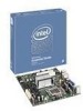
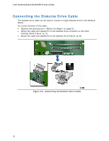
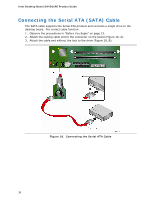
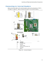
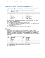
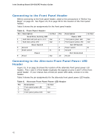
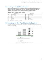
Installing and Replacing Desktop Board Components To restore back panel audio, follow these steps: 1. Observe the precautions in "Before You Begin" on page 23. 2. Turn off all peripheral devices connected to the computer. Turn off the computer and disconnect the AC power cord. 3. Remove the cover. 4. Remove the front panel audio cable. 5. Replace the cover. Connecting to the Serial Port Header See Figure 19, B on page 39 for the location of the serial port header. Table 6 shows the pin assignments for the header. Table 6. Serial Port Header Signal Names Pin Signal Name 1 DCD 3 TXD# 5 Ground 7 RTS 9 RI Pin Signal Name 2 RXD# 4 DTR 6 DSR 8 CTS 10 No Connection Connecting to the Chassis Intrusion Header Figure 19, C on page 39 shows the location of the chassis intrusion header. This header can be connected to a mechanical switch on the chassis to detect if the chassis cover is removed. Table 7 shows the pin assignments for the chassis intrusion header. Table 7. Chassis Intrusion Header Pin Description 1 Intruder 2 Ground 41
-
 1
1 -
2
-
3
-
4
-
5
-
6
-
7
-
8
-
9
-
10
-
11
-
12
-
13
-
14
-
15
-
16
-
17
-
18
-
19
-
20
-
21
-
22
-
23
-
24
-
25
-
26
-
27
-
28
-
29
-
30
-
31
-
32
-
33
-
34
-
35
-
 36
36 -
 37
37 -
 38
38 -
 39
39 -
 40
40 -
 41
41 -
 42
42 -
 43
43 -
 44
44 -
 45
45 -
 46
46 -
47
-
48
-
49
-
50
-
51
-
52
-
53
-
54
-
55
-
56
-
57
-
58
-
59
-
60
-
61
-
62
-
63
-
64
-
65
-
66
 |
 |