Intel D945GCPE Product Guide - Page 43
Connecting to the USB 2.0 Headers, Connecting to the Flexible Audio System
 |
UPC - 735858195195
View all Intel D945GCPE manuals
Add to My Manuals
Save this manual to your list of manuals |
Page 43 highlights
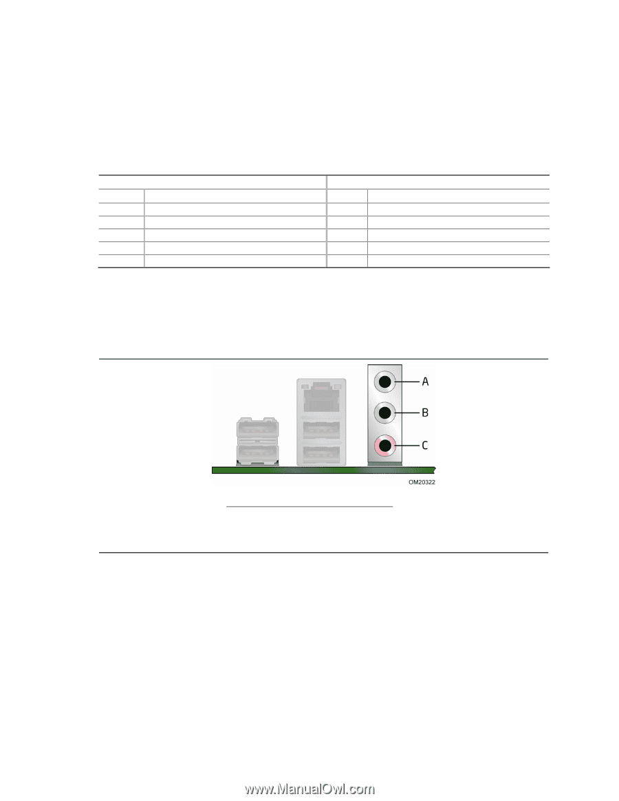
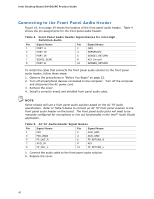
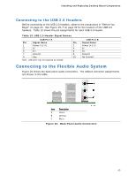
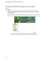
Installing and Replacing Desktop Board Components Connecting to the USB 2.0 Headers Before connecting to the USB 2.0 headers, observe the precautions in "Before You Begin" on page 23. See Figure 19, F on page 39 for the location of the USB 2.0 headers. Table 10 shows the pin assignments for each USB 2.0 header. Table 10. USB 2.0 Header Signal Names USB Port A Pin Signal Name Pin 1 Power (+5 V) 2 3 D- 4 5 D+ 6 7 Ground 8 9 Key 10 Note: USB ports may be assigned as needed. USB Port B Signal Name Power (+5 V) DD+ Ground No Connect Connecting to the Flexible Audio System Figure 20 shows the back panel audio connectors. The default connector assignments are shown in the table. Item Description A Line in B Line out C Mic in Figure 20. Back Panel Audio Connectors 43
-
 1
1 -
2
-
3
-
4
-
5
-
6
-
7
-
8
-
9
-
10
-
11
-
12
-
13
-
14
-
15
-
16
-
17
-
18
-
19
-
20
-
21
-
22
-
23
-
24
-
25
-
26
-
27
-
28
-
29
-
30
-
31
-
32
-
33
-
34
-
35
-
36
-
37
-
 38
38 -
 39
39 -
 40
40 -
 41
41 -
 42
42 -
 43
43 -
 44
44 -
 45
45 -
 46
46 -
 47
47 -
 48
48 -
49
-
50
-
51
-
52
-
53
-
54
-
55
-
56
-
57
-
58
-
59
-
60
-
61
-
62
-
63
-
64
-
65
-
66
 |
 |