Intel DC3217IYE Technical Product Specification - Page 44
States for a One-Color Power LED - sata
 |
View all Intel DC3217IYE manuals
Add to My Manuals
Save this manual to your list of manuals |
Page 44 highlights
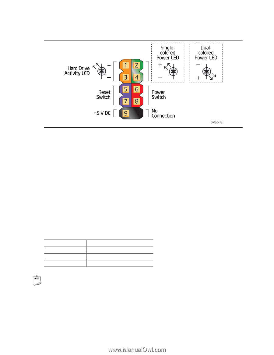
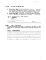
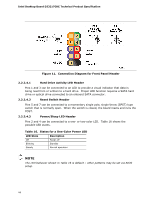
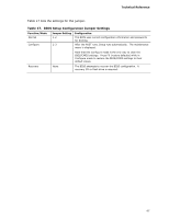
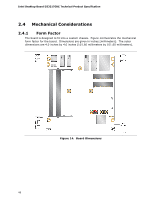
Intel Desktop Board D33217GKE Technical Product Specification Figure 11. Connection Diagram for Front Panel Header 2.2.2.4.1 Hard Drive Activity LED Header Pins 1 and 3 can be connected to an LED to provide a visual indicator that data is being read from or written to a hard drive. Proper LED function requires a SATA hard drive or optical drive connected to an onboard SATA connector. 2.2.2.4.2 Reset Switch Header Pins 5 and 7 can be connected to a momentary single pole, single throw (SPST) type switch that is normally open. When the switch is closed, the board resets and runs the POST. 2.2.2.4.3 Power/Sleep LED Header Pins 2 and 4 can be connected to a one- or two-color LED. Table 16 shows the possible LED states. Table 16. States for a One-Color Power LED LED State Description Off Power off Blinking Standby Steady Normal operation NOTE The LED behavior shown in Table 16 is default - other patterns may be set via BIOS setup. 44
-
 1
1 -
2
-
3
-
4
-
5
-
6
-
7
-
8
-
9
-
10
-
11
-
12
-
13
-
14
-
15
-
16
-
17
-
18
-
19
-
20
-
21
-
22
-
23
-
24
-
25
-
26
-
27
-
28
-
29
-
30
-
31
-
32
-
33
-
34
-
35
-
36
-
37
-
38
-
 39
39 -
 40
40 -
 41
41 -
 42
42 -
 43
43 -
 44
44 -
 45
45 -
 46
46 -
 47
47 -
 48
48 -
 49
49 -
50
-
51
-
52
-
53
-
54
-
55
-
56
-
57
-
58
-
59
-
60
-
61
-
62
-
63
-
64
-
65
-
66
-
67
-
68
-
69
-
70
-
71
-
72
-
73
-
74
-
75
-
76
-
77
-
78
-
79
-
80
-
81
-
82
-
83
-
84
 |
 |