Intel DC3217IYE Technical Product Specification - Page 9

Intel DC3217IYE Manual

Page 9 highlights

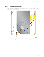
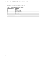
Contents 5.1.5 ENERGY STAR* 5.2, e-Standby, and ErP Compliance 78 5.1.6 Regulatory Compliance Marks (Board Level 79 5.2 Battery Disposal Information 80 Figures 1. Major Board Components (Top 13 2. Major Board Components (Bottom 15 3. Block Diagram 17 4. Memory Channel and SO-DIMM Configuration 21 5. LAN Connector LED Locations 27 6. Thermal Solution and Fan Header 29 7. Location of the Standby Power LED 34 8. Detailed System Memory Address Map 36 9. Back Panel Connectors 38 10. Connectors and Headers (Bottom 39 11. Connection Diagram for Front Panel Header 44 12. Connection Diagram for Front Panel USB 2.0 Dual-Port Header 45 13. Location of the BIOS Configuration Setup Jumper 46 14. Board Dimensions 48 15. Localized High Temperature Zones 51 ix

  • 1
  • 2
  • 3
  • 4
  • 5
  • 6
  • 7
  • 8
  • 9
  • 10
  • 11
  • 12
  • 13
  • 14
  • 15
  • 16
  • 17
  • 18
  • 19
  • 20
  • 21
  • 22
  • 23
  • 24
  • 25
  • 26
  • 27
  • 28
  • 29
  • 30
  • 31
  • 32
  • 33
  • 34
  • 35
  • 36
  • 37
  • 38
  • 39
  • 40
  • 41
  • 42
  • 43
  • 44
  • 45
  • 46
  • 47
  • 48
  • 49
  • 50
  • 51
  • 52
  • 53
  • 54
  • 55
  • 56
  • 57
  • 58
  • 59
  • 60
  • 61
  • 62
  • 63
  • 64
  • 65
  • 66
  • 67
  • 68
  • 69
  • 70
  • 71
  • 72
  • 73
  • 74
  • 75
  • 76
  • 77
  • 78
  • 79
  • 80
  • 81
  • 82
  • 83
  • 84

Contents
ix
5.1.5
ENERGY STAR* 5.2, e-Standby, and ErP Compliance
.................
78
5.1.6
Regulatory Compliance Marks (Board Level)
.............................
79
5.2
Battery Disposal Information
..............................................................
80
Figures
1.
Major Board Components (Top)
..........................................................
13
2.
Major Board Components (Bottom)
.....................................................
15
3.
Block Diagram
..................................................................................
17
4.
Memory Channel and SO-DIMM Configuration
......................................
21
5.
LAN Connector LED Locations
.............................................................
27
6.
Thermal Solution and Fan Header
.......................................................
29
7.
Location of the Standby Power LED
.....................................................
34
8.
Detailed System Memory Address Map
................................................
36
9.
Back Panel Connectors
......................................................................
38
10. Connectors and Headers (Bottom)
......................................................
39
11. Connection Diagram for Front Panel Header
.........................................
44
12. Connection Diagram for Front Panel USB 2.0 Dual-Port Header
...............
45
13. Location of the BIOS Configuration Setup Jumper
.................................
46
14. Board Dimensions
.............................................................................
48
15. Localized High Temperature Zones
.....................................................
51