Intel DG965MQ English Product Guide - Page 49
Connecting to the USB 2.0 Headers, Connecting to the Front Panel Header
 |
View all Intel DG965MQ manuals
Add to My Manuals
Save this manual to your list of manuals |
Page 49 highlights
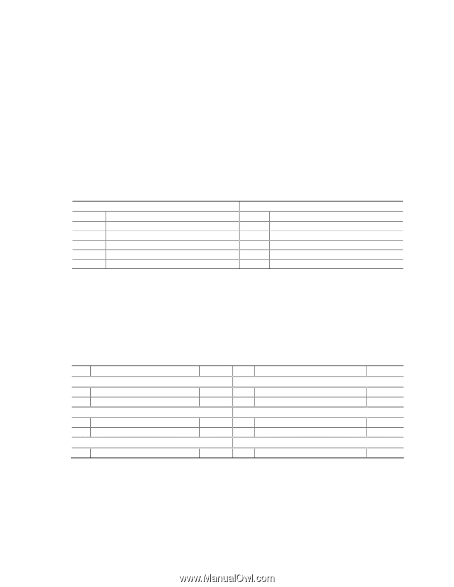
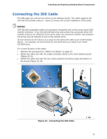
Installing and Replacing Desktop Board Components To restore back panel audio, follow these steps: 1. Observe the precautions in "Before You Begin" on page 27. 2. Turn off all peripheral devices connected to the computer. Turn off the computer and disconnect the AC power cord. 3. Remove the cover. 4. Remove the front panel audio cable. 5. Replace the cover. Connecting to the USB 2.0 Headers Before connecting to the USB 2.0 headers, observe the precautions in "Before You Begin" on page 27. See Figure 25, B on page 47 for the location of the black USB 2.0 headers. Table 7 shows the pin assignments for each USB 2.0 header. Table 7. USB 2.0 Header Signal Names USB Port A Pin Signal Name Pin 1 POWER 2 3 D- 4 5 D+ 6 7 GND 8 9 KEY 10 Note: USB ports may be assigned as needed. USB Port B Signal Name POWER DD+ GND NO CONNECT Connecting to the Front Panel Header Before connecting to the front panel header, observe the precautions in "Before You Begin" on page 27. See Figure 25, F on page 47 for the location of the multi-colored front panel header. Table 8 shows the pin assignments for the front panel header. Table 8. Front Panel Header Pin Description Hard Drive Activity LED 1 Hard disk LED pull-up to +5 V 3 Hard disk active LED Reset Switch 5 Ground 7 Reset switch Power 9 Power In/Out Out Out In Out Pin Description Power LED 2 Front panel green LED 4 Front panel yellow LED On/Off Switch 6 Power switch 8 Ground Not Connected 10 No pin In/Out Out Out In 49
-
 1
1 -
2
-
3
-
4
-
5
-
6
-
7
-
8
-
9
-
10
-
11
-
12
-
13
-
14
-
15
-
16
-
17
-
18
-
19
-
20
-
21
-
22
-
23
-
24
-
25
-
26
-
27
-
28
-
29
-
30
-
31
-
32
-
33
-
34
-
35
-
36
-
37
-
38
-
39
-
40
-
41
-
42
-
43
-
 44
44 -
 45
45 -
 46
46 -
 47
47 -
 48
48 -
 49
49 -
 50
50 -
 51
51 -
 52
52 -
 53
53 -
 54
54 -
55
-
56
-
57
-
58
-
59
-
60
-
61
-
62
-
63
-
64
-
65
-
66
-
67
-
68
-
69
-
70
-
71
-
72
-
73
-
74
-
75
-
76
-
77
-
78
-
79
-
80
-
81
-
82
-
83
-
84
-
85
-
86
-
87
-
88
 |
 |