Intel DH67CF English Product Guide - Page 47
S/PDIF Header, Table 11. Front Panel CIR Receiver Input Header Signal Names
 |
View all Intel DH67CF manuals
Add to My Manuals
Save this manual to your list of manuals |
Page 47 highlights
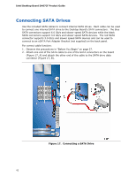
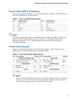
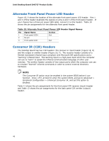
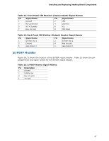
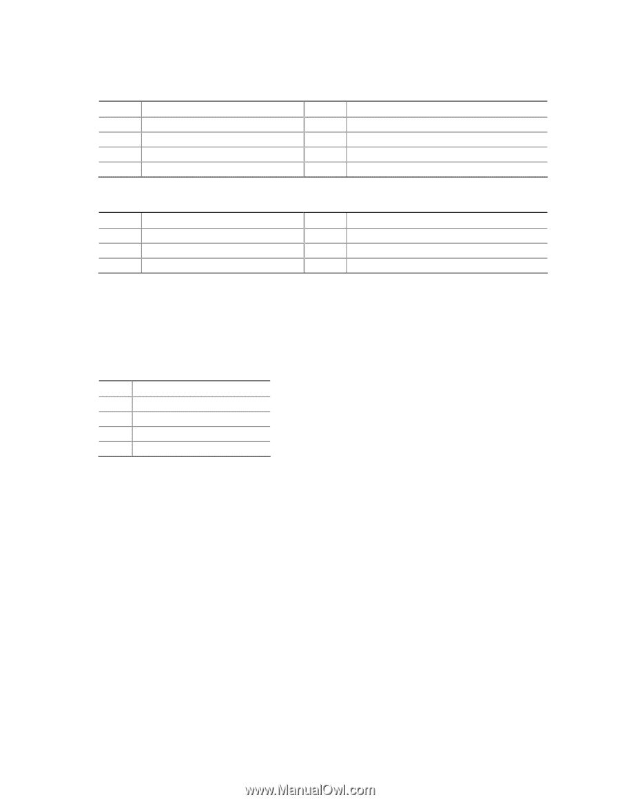
Installing and Replacing Desktop Board Components Table 11. Front Panel CIR Receiver (Input) Header Signal Names Pin Signal Name 1 Ground 3 No Connection 5 +5 V Standby 7 Key (no pin) Pin Signal Name 2 LED 4 Learn-In 6 Vcc 8 CIR Input Table 12. Back Panel CIR Emitter (Output) Header Signal Names Pin Signal Name 1 Emitter Out 1 3 Ground 5 Jack Detect 1 Pin Signal Name 2 Emitter Out 2 4 Key (no pin) 6 Jack Detect 2 S/PDIF Header Figure 18, G shows the location of the S/PDIF output header. Table 13 shows the pin assignments and signal names for the S/PDIF output header. Table 13. S/PDIF Header Signal Names Pin Description 1 Ground 2 S/PDIF Out 3 Key (no pin) 4 +5 VDC 47
-
 1
1 -
2
-
3
-
4
-
5
-
6
-
7
-
8
-
9
-
10
-
11
-
12
-
13
-
14
-
15
-
16
-
17
-
18
-
19
-
20
-
21
-
22
-
23
-
24
-
25
-
26
-
27
-
28
-
29
-
30
-
31
-
32
-
33
-
34
-
35
-
36
-
37
-
38
-
39
-
40
-
41
-
 42
42 -
 43
43 -
 44
44 -
 45
45 -
 46
46 -
 47
47 -
 48
48 -
 49
49 -
 50
50 -
 51
51 -
 52
52 -
53
-
54
-
55
-
56
-
57
-
58
-
59
-
60
-
61
-
62
-
63
-
64
-
65
-
66
-
67
-
68
-
69
-
70
-
71
-
72
-
73
-
74
-
75
-
76
 |
 |
Installing and Replacing Desktop Board Components
47
Table 11. Front Panel CIR Receiver (Input) Header Signal Names
Pin
Signal Name
Pin
Signal Name
1
Ground
2
LED
3
No Connection
4
Learn-In
5
+5 V Standby
6
Vcc
7
Key (no pin)
8
CIR Input
Table 12. Back Panel CIR Emitter (Output) Header Signal Names
Pin
Signal Name
Pin
Signal Name
1
Emitter Out 1
2
Emitter Out 2
3
Ground
4
Key (no pin)
5
Jack Detect 1
6
Jack Detect 2
S/PDIF Header
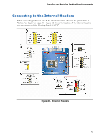
Figure 18, G shows the location of the S/PDIF output header.
Table 13 shows the pin
assignments and signal names for the S/PDIF output header.
Table 13. S/PDIF Header Signal Names
Pin
Description
1
Ground
2
S/PDIF Out
3
Key (no pin)
4
+5 VDC