Intel DQ57TM Intel Desktop Board DQ57TM Product Guide English - Page 43
Installing and Removing System Memory, Guidelines for Dual Channel Memory Configuration
 |
View all Intel DQ57TM manuals
Add to My Manuals
Save this manual to your list of manuals |
Page 43 highlights
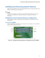
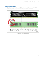
Installing and Replacing Desktop Board Components Installing and Removing System Memory Desktop board DQ57TM has four 240-pin DDR3 DIMM sockets arranged as DIMM 0 and DIMM 1 in both Channel A and Channel B. NOTE A DIMM must be present in at least one of the DIMM 0 sockets when you are using only one or two DIMMs with a processor that does not support Intel Graphics Technology. Guidelines for Dual Channel Memory Configuration Before installing DIMMs, read and follow these guidelines for dual channel memory configuration. Two or Four DIMMs Install a matched pair of DIMMs equal in speed and size (see Figure 15) in the DIMM 0 (blue) sockets of channels A and B. Figure 15. Example Dual Channel Memory Configuration with Two DIMMs 43
-
 1
1 -
2
-
3
-
4
-
5
-
6
-
7
-
8
-
9
-
10
-
11
-
12
-
13
-
14
-
15
-
16
-
17
-
18
-
19
-
20
-
21
-
22
-
23
-
24
-
25
-
26
-
27
-
28
-
29
-
30
-
31
-
32
-
33
-
34
-
35
-
36
-
37
-
 38
38 -
 39
39 -
 40
40 -
 41
41 -
 42
42 -
 43
43 -
 44
44 -
 45
45 -
 46
46 -
 47
47 -
 48
48 -
49
-
50
-
51
-
52
-
53
-
54
-
55
-
56
-
57
-
58
-
59
-
60
-
61
-
62
-
63
-
64
-
65
-
66
-
67
-
68
-
69
-
70
-
71
-
72
-
73
-
74
-
75
-
76
-
77
-
78
-
79
-
80
-
81
-
82
-
83
-
84
-
85
-
86
-
87
-
88
 |
 |
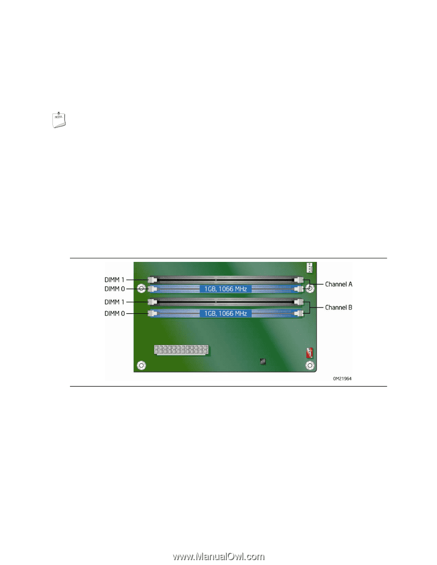
Installing and Replacing Desktop Board Components
43
Installing and Removing System Memory
Desktop board DQ57TM has four 240-pin DDR3 DIMM sockets arranged as DIMM 0 and
DIMM 1 in both Channel A and Channel B.
NOTE
A DIMM must be present in at least one of the DIMM 0 sockets when you are using
only one or two DIMMs with a processor that does not support Intel Graphics
Technology.
Guidelines for Dual Channel Memory Configuration
Before installing DIMMs, read and follow these guidelines for dual channel memory
configuration.
Two or Four DIMMs
Install a matched pair of DIMMs equal in speed and size (see Figure 15) in the DIMM 0
(blue) sockets of channels A and B.
Figure 15.
Example Dual Channel Memory Configuration with Two DIMMs