Intel DQ67SW English Product Guide - Page 52
Internal Mono Speaker Header, Serial Header, Chassis Intrusion Header, Table 9. Serial Port Header
 |
View all Intel DQ67SW manuals
Add to My Manuals
Save this manual to your list of manuals |
Page 52 highlights
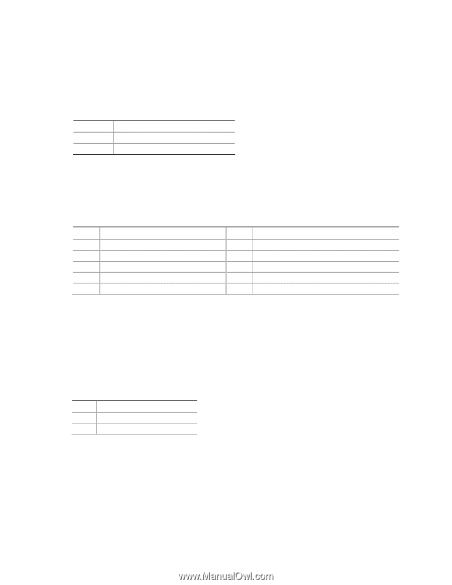
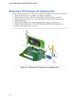
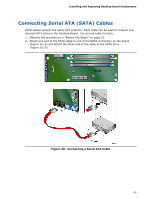
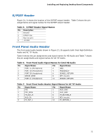
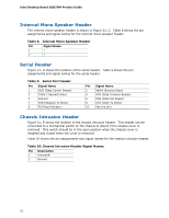
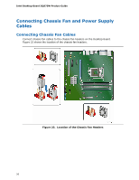
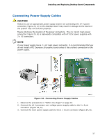
Intel Desktop Board DQ67SW Product Guide Internal Mono Speaker Header The internal mono speaker header is shown in Figure 21, C. Table 8 shows the pin assignments and signal names for the internal mono speaker header. Table 8. Internal Mono Speaker Header Pin Signal Name 1 − 2 + Serial Header Figure 21, D shows the location of the serial header. Table 9 shows the pin assignments and signal names for the serial header. Table 9. Serial Port Header Pin Signal Name 1 DCD (Data Carrier Detect) 3 TXD# (Transmit Data) 5 Ground 7 RTS (Request To Send) 9 RI (Ring Indicator) Pin Signal Name 2 RXD# (Receive Data) 4 DTR (Data Terminal Ready) 6 DSR (Data Set Ready) 8 CTS (Clear To Send) 10 Key (no pin) Chassis Intrusion Header Figure 21, E shows the location of the chassis intrusion header. This header can be connected to a mechanical switch on the chassis to detect if the chassis cover is removed. This switch should be in the open position when the chassis cover is installed and closed when the cover is removed. Table 10 shows the pin assignments and signal names for the chassis intrusion header. Table 10. Chassis Intrusion Header Signal Names Pin Description 1 Intruder# 2 Ground 52
-
 1
1 -
2
-
3
-
4
-
5
-
6
-
7
-
8
-
9
-
10
-
11
-
12
-
13
-
14
-
15
-
16
-
17
-
18
-
19
-
20
-
21
-
22
-
23
-
24
-
25
-
26
-
27
-
28
-
29
-
30
-
31
-
32
-
33
-
34
-
35
-
36
-
37
-
38
-
39
-
40
-
41
-
42
-
43
-
44
-
45
-
46
-
 47
47 -
 48
48 -
 49
49 -
 50
50 -
 51
51 -
 52
52 -
 53
53 -
 54
54 -
 55
55 -
 56
56 -
 57
57 -
58
-
59
-
60
-
61
-
62
-
63
-
64
-
65
-
66
-
67
-
68
-
69
-
70
-
71
-
72
-
73
-
74
-
75
-
76
-
77
-
78
-
79
-
80
-
81
-
82
-
83
-
84
-
85
-
86
 |
 |