Intel DQ67SW English Product Guide - Page 7

s, Intel Desktop Board DQ67SW China RoHS Material Self Declaration Table - compatible processors

Page 7 highlights

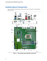
Contents Product Ecology Statements 77 Recycling Considerations 77 China RoHS 80 EMC Regulations 81 FCC Declaration of Conformity 81 Canadian Department of Communications Compliance Statement 82 Japan VCCI Statement 82 Korea Class B Statement 83 Ensure Electromagnetic Compatibility (EMC) Compliance 83 Product Certifications 84 Board-Level Certifications 84 Chassis- and Component-Level Certifications 85 ENERGY STAR*, e-Standby, and ErP Compliance 85 Figures 1. Intel Desktop Board DQ67SW Components 12 2. LAN Status LEDs 18 3. Location of the Intel MEBX Reset Header 27 4. Location of the Standby Power Indicator 31 5. Installing the I/O Shield 35 6. Intel Desktop Board DQ67SW Mounting Screw Hole Locations 36 7. Unlatch the Socket Lever 37 8. Lift the Load Plate 38 9. Remove the Processor from the Protective Cover 39 10. Install the Processor 39 11. Secure the Load Plate in Place 40 12. Connecting the Processor Fan Heat Sink Power Cable to the Processor Fan Header 41 13. Example Dual Channel Memory Configuration with Two DIMMs 42 14. Example Dual Channel Memory Configuration with Four DIMMs 42 15. Example Dual Channel Memory Configuration with Three DIMMs 43 16. Use DDR3 DIMMs 44 17. Installing a DIMM 45 18. Installing a PCI Express x16 Graphics Card 47 19. Removing a PCI Express x16 Graphics Card 48 20. Connecting a Serial ATA Cable 49 21. Internal Headers 50 22. Back Panel Audio Connectors 55 23. Location of the Chassis Fan Headers 56 24. Connecting Power Supply Cables 57 25. Location of the BIOS Configuration Jumper Block 58 26. Removing the Battery 65 27. Intel Desktop Board DQ67SW China RoHS Material Self Declaration Table 80 vii

  • 1
  • 2
  • 3
  • 4
  • 5
  • 6
  • 7
  • 8
  • 9
  • 10
  • 11
  • 12
  • 13
  • 14
  • 15
  • 16
  • 17
  • 18
  • 19
  • 20
  • 21
  • 22
  • 23
  • 24
  • 25
  • 26
  • 27
  • 28
  • 29
  • 30
  • 31
  • 32
  • 33
  • 34
  • 35
  • 36
  • 37
  • 38
  • 39
  • 40
  • 41
  • 42
  • 43
  • 44
  • 45
  • 46
  • 47
  • 48
  • 49
  • 50
  • 51
  • 52
  • 53
  • 54
  • 55
  • 56
  • 57
  • 58
  • 59
  • 60
  • 61
  • 62
  • 63
  • 64
  • 65
  • 66
  • 67
  • 68
  • 69
  • 70
  • 71
  • 72
  • 73
  • 74
  • 75
  • 76
  • 77
  • 78
  • 79
  • 80
  • 81
  • 82
  • 83
  • 84
  • 85
  • 86

Contents
vii
Product Ecology Statements
................................................................................
77
Recycling Considerations
.............................................................................
77
China RoHS
...............................................................................................
80
EMC Regulations
................................................................................................
81
FCC Declaration of Conformity
......................................................................
81
Canadian Department of Communications Compliance Statement
......................
82
Japan VCCI Statement
................................................................................
82
Korea Class B Statement
.............................................................................
83
Ensure Electromagnetic Compatibility (EMC) Compliance
..................................
83
Product Certifications
..........................................................................................
84
Board-Level Certifications
............................................................................
84
Chassis- and Component-Level Certifications
..................................................
85
ENERGY STAR*, e-Standby, and ErP Compliance
....................................................
85
Figures
1. Intel Desktop Board DQ67SW Components
.......................................................
12
2. LAN Status LEDs
..........................................................................................
18
3.
Location of the Intel MEBX Reset Header
..........................................................
27
4.
Location of the Standby Power Indicator
..........................................................
31
5. Installing the I/O Shield
................................................................................
35
6.
Intel Desktop Board DQ67SW Mounting Screw Hole Locations
.............................
36
7. Unlatch the Socket Lever
...............................................................................
37
8. Lift the Load Plate
.........................................................................................
38
9.
Remove the Processor from the Protective Cover
..............................................
39
10. Install the Processor
.....................................................................................
39
11. Secure the Load Plate in Place
........................................................................
40
12. Connecting the Processor Fan Heat Sink Power Cable to the Processor
Fan Header
..................................................................................................
41
13. Example Dual Channel Memory Configuration with Two DIMMs
...........................
42
14. Example Dual Channel Memory Configuration with Four DIMMs
...........................
42
15. Example Dual Channel Memory Configuration with Three DIMMs
.........................
43
16. Use DDR3 DIMMs
.........................................................................................
44
17. Installing a DIMM
.........................................................................................
45
18. Installing a PCI Express x16 Graphics Card
......................................................
47
19. Removing a PCI Express x16 Graphics Card
......................................................
48
20. Connecting a Serial ATA Cable
........................................................................
49
21. Internal Headers
..........................................................................................
50
22. Back Panel Audio Connectors
.........................................................................
55
23. Location of the Chassis Fan Headers
................................................................
56
24. Connecting Power Supply Cables
....................................................................
57
25. Location of the BIOS Configuration Jumper Block
..............................................
58
26. Removing the Battery
...................................................................................
65
27. Intel Desktop Board DQ67SW China RoHS Material Self Declaration Table
.............
80