Intel DQ965WC English Product Guide - Page 18
RJ-45 LAN Connector LEDs, Table 4. LAN Connector LED States
 |
View all Intel DQ965WC manuals
Add to My Manuals
Save this manual to your list of manuals |
Page 18 highlights
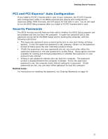
Intel Desktop Board DQ965WC Product Guide RJ-45 LAN Connector LEDs Two LEDs are built into the RJ-45 LAN connector located on the back panel (see Figure 2). These LEDs indicate the status of the LAN. Figure 2. LAN Connector LEDs Table 4 describes the LED states when the board is powered up and the LAN subsystem is operating. Table 4. LAN Connector LED States LED A B LED Color Green N/A Green Yellow LED State Off On Blinking Off On On Indicates LAN link is not established LAN link is established LAN activity is occurring 10 Mb/s data rate 100 Mb/s data rate 1000 Mb/s data rate 18
-
 1
1 -
2
-
3
-
4
-
5
-
6
-
7
-
8
-
9
-
10
-
11
-
12
-
 13
13 -
 14
14 -
 15
15 -
 16
16 -
 17
17 -
 18
18 -
 19
19 -
 20
20 -
 21
21 -
 22
22 -
 23
23 -
24
-
25
-
26
-
27
-
28
-
29
-
30
-
31
-
32
-
33
-
34
-
35
-
36
-
37
-
38
-
39
-
40
-
41
-
42
-
43
-
44
-
45
-
46
-
47
-
48
-
49
-
50
-
51
-
52
-
53
-
54
-
55
-
56
-
57
-
58
-
59
-
60
-
61
-
62
-
63
-
64
-
65
-
66
-
67
-
68
-
69
-
70
-
71
-
72
-
73
-
74
-
75
-
76
-
77
-
78
-
79
-
80
 |
 |
Intel Desktop Board DQ965WC Product Guide
18
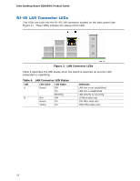
RJ-45 LAN Connector LEDs
Two LEDs are built into the RJ-45 LAN connector located on the back panel (see
Figure 2).
These LEDs indicate the status of the LAN.
Figure 2.
LAN Connector LEDs
Table 4 describes the LED states when the board is powered up and the LAN
subsystem is operating.
Table 4. LAN Connector LED States
LED
LED Color
LED State
Indicates
Off
LAN link is not established
On
LAN link is established
A
Green
Blinking
LAN activity is occurring
N/A
Off
10 Mb/s data rate
Green
On
100 Mb/s data rate
B
Yellow
On
1000 Mb/s data rate