Intel DQ965WC English Product Guide - Page 55
Back Panel Connectors
 |
View all Intel DQ965WC manuals
Add to My Manuals
Save this manual to your list of manuals |
Page 55 highlights
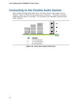
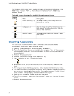
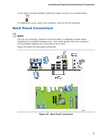
Installing and Replacing Desktop Board Components 12. To restore normal operation, place the jumper on pins 1-2 as shown below. 13. Replace the cover, plug in the computer, and turn on the computer. Back Panel Connectors NOTE The line out connector, located on the back panel, is designed to power either headphones or amplified speakers only. Poor audio quality may occur if passive (non-amplified) speakers are connected to this output. Figure 29 shows the back panel connectors. Figure 29. Back Panel Connectors 55
-
 1
1 -
2
-
3
-
4
-
5
-
6
-
7
-
8
-
9
-
10
-
11
-
12
-
13
-
14
-
15
-
16
-
17
-
18
-
19
-
20
-
21
-
22
-
23
-
24
-
25
-
26
-
27
-
28
-
29
-
30
-
31
-
32
-
33
-
34
-
35
-
36
-
37
-
38
-
39
-
40
-
41
-
42
-
43
-
44
-
45
-
46
-
47
-
48
-
49
-
 50
50 -
 51
51 -
 52
52 -
 53
53 -
 54
54 -
 55
55 -
 56
56 -
 57
57 -
 58
58 -
 59
59 -
 60
60 -
61
-
62
-
63
-
64
-
65
-
66
-
67
-
68
-
69
-
70
-
71
-
72
-
73
-
74
-
75
-
76
-
77
-
78
-
79
-
80
 |
 |
Installing and Replacing Desktop Board Components
55
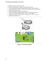
12.
To restore normal operation, place the jumper on pins 1-2 as shown below.
13.
Replace the cover, plug in the computer, and turn on the computer.
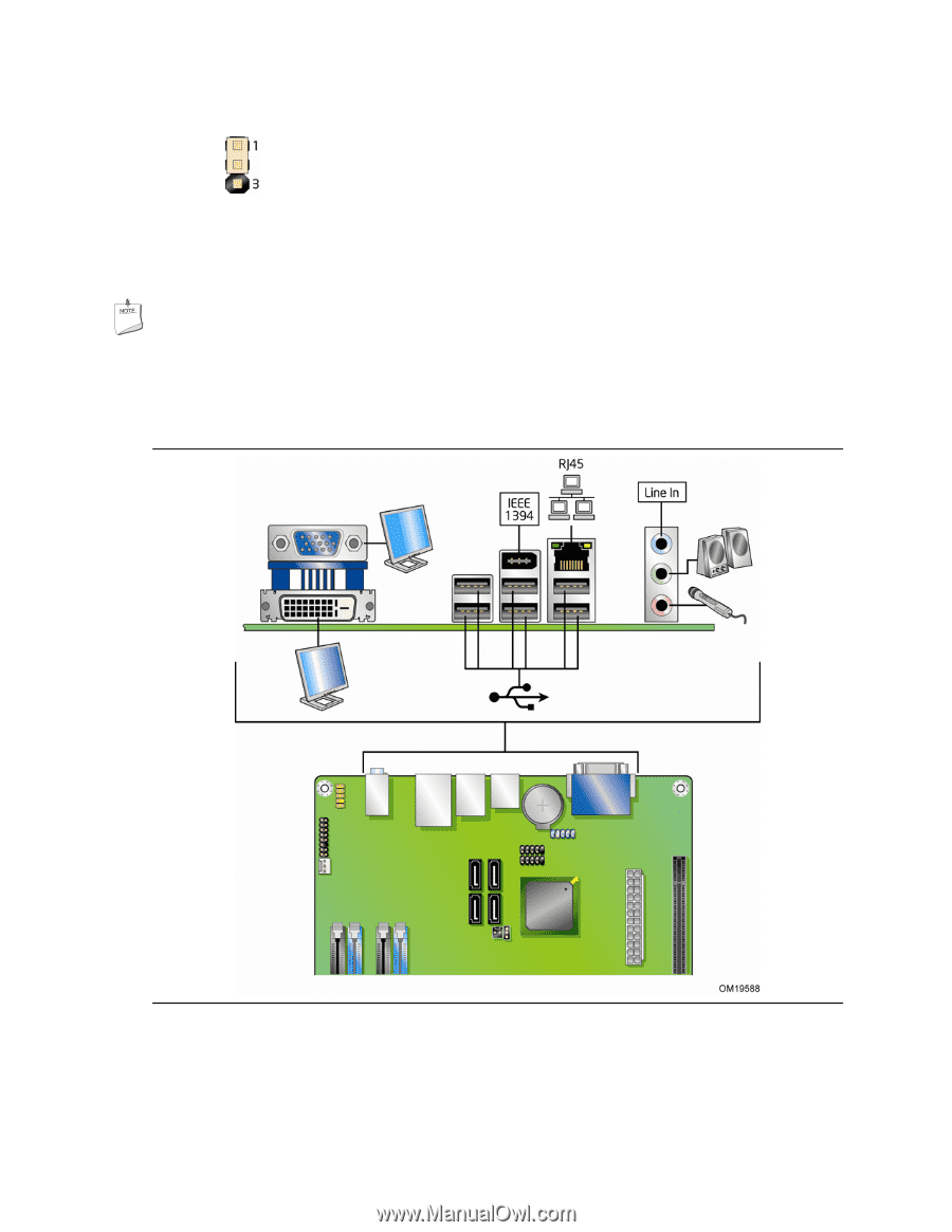
Back Panel Connectors
NOTE
The line out connector, located on the back panel, is designed to power either
headphones or amplified speakers only.
Poor audio quality may occur if passive
(non-amplified) speakers are connected to this output.
Figure 29 shows the back panel connectors.
Figure 29.
Back Panel Connectors