Intel DZ68PL Technical product specification - Page 14
Table 2., Components Shown
 |
View all Intel DZ68PL manuals
Add to My Manuals
Save this manual to your list of manuals |
Page 14 highlights
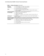
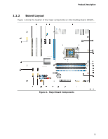
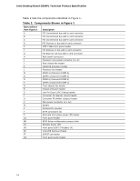
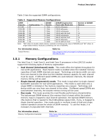
Intel Desktop Board DZ68PL Technical Product Specification Table 2 lists the components identified in Figure 1. Table 2. Components Shown in Figure 1 Item/callout from Figure 1 A B Description PCI Conventional bus add-in card connector PCI Conventional bus add-in card connector C PCI Conventional bus add-in card connector D PCI Express x1 bus add-in card connector E IEEE 1394a front panel header F PCI Express x1 bus add-in card connector G PCI Express x16 bus add-in card connector H Back panel connectors I Processor core power connector (2 x 2) J Rear chassis fan header K LGA1155 processor socket L Processor fan header M DIMM 3 (Channel A DIMM 0) N DIMM 1 (Channel A DIMM 1) O DIMM 4 (Channel B DIMM 0) P DIMM 2 (Channel B DIMM 1) Q Front chassis fan header R Chassis intrusion header S Low Pin Count (LPC) Debug header T Consumer IR receiver (input) header U Consumer IR emitter (output) header V Main power connector (2 x 12) W Battery X Piezoelectric speaker Y SATA connectors (5) Z Alternate front panel power LED header AA Front panel header BB BIOS Setup configuration jumper block CC Standby power LED DD Front panel USB 2.0 headers (4) EE Intel Z68 Express Chipset FF S/PDIF out header GG Front panel audio header 14
-
 1
1 -
2
-
3
-
4
-
5
-
6
-
7
-
8
-
 9
9 -
 10
10 -
 11
11 -
 12
12 -
 13
13 -
 14
14 -
 15
15 -
 16
16 -
 17
17 -
 18
18 -
 19
19 -
20
-
21
-
22
-
23
-
24
-
25
-
26
-
27
-
28
-
29
-
30
-
31
-
32
-
33
-
34
-
35
-
36
-
37
-
38
-
39
-
40
-
41
-
42
-
43
-
44
-
45
-
46
-
47
-
48
-
49
-
50
-
51
-
52
-
53
-
54
-
55
-
56
-
57
-
58
-
59
-
60
-
61
-
62
-
63
-
64
-
65
-
66
-
67
-
68
-
69
-
70
-
71
-
72
-
73
-
74
-
75
-
76
-
77
-
78
-
79
-
80
-
81
-
82
-
83
-
84
-
85
-
86
-
87
-
88
-
89
-
90
-
91
-
92
 |
 |