Intel DZ68ZV Technical Product Specification - Page 26
Audio Subsystem
 |
View all Intel DZ68ZV manuals
Add to My Manuals
Save this manual to your list of manuals |
Page 26 highlights
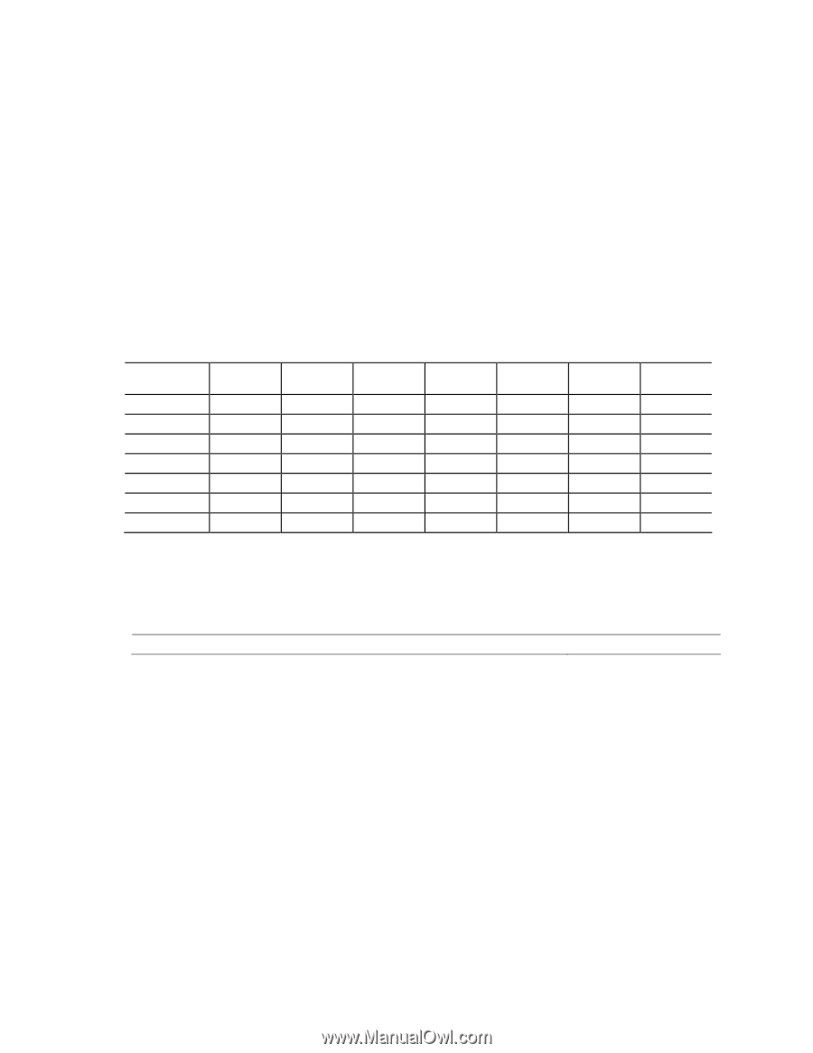
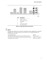
Intel Desktop Board DZ68ZV Technical Product Specification 1.9 Audio Subsystem The board supports the Intel High Definition Audio subsystem based on the Realtek ALC892 audio codec. The audio subsystem supports the following features: • Advanced jack sense for the back panel audio jacks that enables the audio codec to recognize the device that is connected to an audio port. The back panel audio jacks are capable of retasking according to the user's definition, or can be automatically switched depending on the recognized device type. • Stereo input and output for all back panel jacks • Line out and Mic in functions for front panel audio jacks • A signal-to-noise (S/N) ratio of 90 dB Table 4 lists the supported functions of the front panel and back panel audio jacks. Table 4. Audio Jack Support Audio Jack Microphone Headphones FP Green Default FP Pink Default Rear Blue Rear Green Ctrl panel Rear Pink Default Rear Black Rear Orange Front Speaker Default Line In Default Rear Surround Center/ Sub Side Surround Default Default Ctrl panel 1.9.1 Audio Subsystem Software Audio software and drivers are available from Intel's World Wide Web site. For information about Obtaining audio software and drivers Refer to Section 1.3, page 16 1.9.2 Audio Subsystem Components The audio subsystem includes the following components: • Intel Z68 Express Chipset • Realtek ALC892 audio codec • Front panel audio header that supports Intel HD audio and AC '97 audio (a 2 x 5- pin header that provides mic in and line out signals for front panel audio connectors) (yellow) • S/PDIF digital audio out header (1 x 4-pin header) (yellow) • S/PDIF digital audio out connector on the back panel • 5-port analog audio input/output stack on the back panel The back panel audio connectors are configurable through the audio device drivers. The available configurable back panel audio connectors are shown in Figure 4. 26
-
 1
1 -
2
-
3
-
4
-
5
-
6
-
7
-
8
-
9
-
10
-
11
-
12
-
13
-
14
-
15
-
16
-
17
-
18
-
19
-
20
-
 21
21 -
 22
22 -
 23
23 -
 24
24 -
 25
25 -
 26
26 -
 27
27 -
 28
28 -
 29
29 -
 30
30 -
 31
31 -
32
-
33
-
34
-
35
-
36
-
37
-
38
-
39
-
40
-
41
-
42
-
43
-
44
-
45
-
46
-
47
-
48
-
49
-
50
-
51
-
52
-
53
-
54
-
55
-
56
-
57
-
58
-
59
-
60
-
61
-
62
-
63
-
64
-
65
-
66
-
67
-
68
-
69
-
70
-
71
-
72
-
73
-
74
-
75
-
76
-
77
-
78
-
79
-
80
-
81
-
82
-
83
-
84
-
85
-
86
-
87
-
88
-
89
-
90
-
91
-
92
-
93
-
94
-
95
 |
 |