Intel IXM5414E User Guide - Page 29
Switch Management and Operating Concepts, Intel® Blade Server Ethernet Switch Module IXM5414E
 |
UPC - 735858185493
View all Intel IXM5414E manuals
Add to My Manuals
Save this manual to your list of manuals |
Page 29 highlights
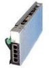
4 Switch Management and Operating Concepts This chapter discusses many of the concepts and features used to manage the Intel® Blade Server Ethernet Switch Module IXM5414E and the concepts necessary to understand how it functions. In addition, this chapter explains many important points regarding these features. Configuring the switch module to implement these concepts and use its many features is discussed in detail in the following chapters. Intel® Blade Server Ethernet Switch Module IXM5414E overview This section provides information that you should be familiar with when managing and configuring the internal switch modules. If you are familiar with Ethernet switches, you will recognize the industry-standard parameters and terminology used in this document. However, it is important that you also understand the operating environment of the SB-HE platform with regard to the internal switches. IXM5414E switch modules are hot-swappable subsystems that provide Ethernet switching capabilities within the chassis of the SB-HE platform. The primary purpose of the switch module is to provide Ethernet interconnectivity among the processor blades, management modules and the external network infrastructure. The SB-HE platform may be configured with up to four independent switch modules, supporting up to fourteen server blades. Ports 1 through 14 on the switch module correspond to server blades 1 through 14, respectively (numbered left to right when viewed from the front of the chassis). Each switch module has four external 10/100/1000 Mbps Ethernet ports for connection to the external network infrastructure. These ports are identified as Ext.1, Ext.2, Ext.3 and Ext.4 in the switch module configuration menus and are labeled 1 through 4 on the switch module (see Chapter 3 "Information Panel LEDs and External Ports" on page 17 for an illustration). Depending on the application, the external Ethernet interfaces can be configured to meet a variety of requirements for bandwidth or function.The IXM5414E switch module has been pre-configured with default parameter settings that can be used with some typical installations. Most installations will need some configuration of parameters. Information on initial software configuration can be found in "Remotely managing the IXM5414E switch module" on page 158 and "IXM5414E switch module system commands" on page 160. Chassis configuration and operation Each IXM5414E switch module is an integral subsystem within an overall SB-HE platform. For additional platform level information, see the applicable Installation and User's Guide publications on the Resource CD. Each chassis includes one or two management modules (MM) as the central element for overall chassis management and control. The switch module includes 100-Mbps internal Ethernet ports that can only be accessed by the management modules. To prevent inadvertent changes, this management port is "hidden" and does not appear in the port configuration and status screens. The factory default settings will only permit management and control access to the switch module through the 10/100 Mbps Ethernet port on the management module. You can use the four external 10/100/1000 Mbps Ethernet ports on the switch module for management and control of the 19
-
 1
1 -
2
-
3
-
4
-
5
-
6
-
7
-
8
-
9
-
10
-
11
-
12
-
13
-
14
-
15
-
16
-
17
-
18
-
19
-
20
-
21
-
22
-
23
-
 24
24 -
 25
25 -
 26
26 -
 27
27 -
 28
28 -
 29
29 -
 30
30 -
 31
31 -
 32
32 -
 33
33 -
 34
34 -
35
-
36
-
37
-
38
-
39
-
40
-
41
-
42
-
43
-
44
-
45
-
46
-
47
-
48
-
49
-
50
-
51
-
52
-
53
-
54
-
55
-
56
-
57
-
58
-
59
-
60
-
61
-
62
-
63
-
64
-
65
-
66
-
67
-
68
-
69
-
70
-
71
-
72
-
73
-
74
-
75
-
76
-
77
-
78
-
79
-
80
-
81
-
82
-
83
-
84
-
85
-
86
-
87
-
88
-
89
-
90
-
91
-
92
-
93
-
94
-
95
-
96
-
97
-
98
-
99
-
100
-
101
-
102
-
103
-
104
-
105
-
106
-
107
-
108
-
109
-
110
-
111
-
112
-
113
-
114
-
115
-
116
-
117
-
118
-
119
-
120
-
121
-
122
-
123
-
124
-
125
-
126
-
127
-
128
-
129
-
130
-
131
-
132
-
133
-
134
-
135
-
136
-
137
-
138
-
139
-
140
-
141
-
142
-
143
-
144
-
145
-
146
-
147
-
148
-
149
-
150
-
151
-
152
-
153
-
154
-
155
-
156
-
157
-
158
-
159
-
160
-
161
-
162
-
163
-
164
-
165
-
166
-
167
-
168
-
169
-
170
-
171
-
172
-
173
-
174
-
175
-
176
-
177
-
178
-
179
-
180
-
181
-
182
-
183
-
184
-
185
-
186
-
187
-
188
-
189
-
190
-
191
-
192
-
193
-
194
-
195
-
196
-
197
-
198
-
199
-
200
-
201
-
202
-
203
-
204
-
205
-
206
-
207
-
208
-
209
-
210
-
211
-
212
-
213
-
214
-
215
-
216
-
217
-
218
-
219
-
220
-
221
-
222
-
223
-
224
-
225
-
226
-
227
-
228
-
229
-
230
-
231
-
232
-
233
-
234
-
235
-
236
-
237
-
238
-
239
-
240
-
241
-
242
-
243
-
244
-
245
-
246
-
247
-
248
-
249
-
250
-
251
-
252
-
253
-
254
-
255
-
256
-
257
-
258
-
259
-
260
-
261
-
262
-
263
-
264
-
265
-
266
-
267
-
268
-
269
-
270
-
271
-
272
-
273
-
274
-
275
-
276
-
277
-
278
-
279
-
280
-
281
-
282
-
283
-
284
-
285
-
286
-
287
-
288
-
289
-
290
-
291
-
292
-
293
-
294
 |
 |
