Intel S3200SH Product Specification - Page 18
Super I/O controller SMSC* SCH5027D providing all PC-compatible I/O floppy - motherboard
 |
View all Intel S3200SH manuals
Add to My Manuals
Save this manual to your list of manuals |
Page 18 highlights
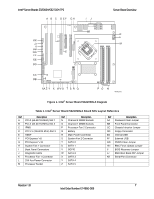
Server Board Overview Intel® Server Boards S3200SH/S3210SH TPS o One 4-pin SATA RAID Key o One 2-pin intrusion detection ƒ BIOS o EFI BIOS ƒ Power Management o Support for Power Management of all capable components o ACPI-compliant motherboard and BIOS o Sleep Switch and dual mode LED indicator ƒ Manufacturing o Surface mount technology. Single-sided assembly for LC/V board SKUs and double-sided assembly for the LX board SKU o Six-layer PCB ƒ Form Factor o ATX 2.0, 12-inches x 9.6-inches, 1U thermally optimized, and SSI TEB Rev 2.11 compatible. ƒ Universal Serial Bus 2.0 (USB) o Two external USB ports (located at the rear panel) with an additional internal header providing two optional USB ports for front panel support o Supports wake-up from ACPI sleeping states S1 and S4 (S3 is not supported) o Supports legacy keyboard/mouse connections when using a PS/2-USB dongle ƒ LPC (Low Pin Count) bus segment with one embedded device o Super I/O controller (SMSC* SCH5027D) providing all PC-compatible I/O (floppy, serial, keyboard, mouse, two serial com ports) and integrated hardware monitoring. ƒ SSI-compliant connectors for SSI interface support ƒ Standard 24-pin SSI front panel, 2x12 main power connector, and 2x4 CPU power connector ƒ Fan Support o Five general purpose 4-pin fan headers ƒ One 4-pin processor fan header (active heat sink required) ƒ Four 4-pin system fan headers (3-pin fans are compatible with all fan headers. You should only use 4-pin fans with Sys Fan 1 and Sys Fan 2; Sys Fan 3 and Sys Fan 4 are connected to the PWM processor, which is programmed to work with the 4-pin active heat sink fan.) ƒ Diagnostic LEDs to display POST (Power-on Self-Test) code indicators during boot ƒ Onboard SATA RAID o Intel® Matrix Storage Technology supports software SATA RAID 0, 1, 10 and 5; Microsoft Windows* driver support only. The following figure shows the board layout of the LX board SKU. A letter (shown in Table 1) identifies each connector and major component. 6 Revision 1.8 Intel Order Number: E14960-009
-
 1
1 -
2
-
3
-
4
-
5
-
6
-
7
-
8
-
9
-
10
-
11
-
12
-
 13
13 -
 14
14 -
 15
15 -
 16
16 -
 17
17 -
 18
18 -
 19
19 -
 20
20 -
 21
21 -
 22
22 -
 23
23 -
24
-
25
-
26
-
27
-
28
-
29
-
30
-
31
-
32
-
33
-
34
-
35
-
36
-
37
-
38
-
39
-
40
-
41
-
42
-
43
-
44
-
45
-
46
-
47
-
48
-
49
-
50
-
51
-
52
-
53
-
54
-
55
-
56
-
57
-
58
-
59
-
60
-
61
-
62
-
63
-
64
-
65
-
66
-
67
-
68
-
69
-
70
-
71
-
72
-
73
-
74
-
75
-
76
-
77
-
78
-
79
-
80
-
81
-
82
-
83
-
84
-
85
-
86
-
87
-
88
-
89
-
90
-
91
-
92
-
93
-
94
-
95
-
96
-
97
-
98
-
99
-
100
-
101
-
102
-
103
-
104
-
105
-
106
-
107
-
108
-
109
-
110
-
111
-
112
-
113
-
114
-
115
-
116
-
117
-
118
-
119
-
120
-
121
-
122
-
123
-
124
-
125
-
126
-
127
-
128
 |
 |
