Intel S3200SH Product Specification - Page 20
Intel, Server Board S3210SHLC Diagram, Table 2. Intel, Server Board S3210SHLC Layout
 |
View all Intel S3200SH manuals
Add to My Manuals
Save this manual to your list of manuals |
Page 20 highlights
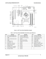
Server Board Overview Intel® Server Boards S3200SH/S3210SH TPS The following figure shows the board layout of the LC board SKU. A letter identifies each connector and major component (shown in Table 2). AB C D EF GH LL KK I JJ J II HH K GG FF EE DD CC BB AA Z Y X WV U T S R Q P O NM L AF002304 Figure 2. Intel® Server Board S3210SHLC Diagram Table 2. Intel® Server Board S3210SHLC Layout Reference Ref Description A PCI (32-bit/33 MHz) Slot 1 B PCI (32-bit/33 MHz) Slot 2 C PCI Express* x8 (x8 lane) D PCI Express* x8 (x4 lane) E PCI Express* x16 F System Fan 1 Connector G Back Panel Connectors H Diagnostic LEDs I Processor Fan 1 Connector J 2X4 Aux Power Connector K Processor Socket L Channel 2 DIMM Sockets M Channel 1 DIMM Sockets Ref Description N System Fan4 Connector O System Fan3 Connector P Battery Q Main Power Connector R System Fan2 S Floppy Connector T SGPIO U SATA 0 V HSBP W SATA1 X SATA2 Y IPMB Z Front Panel Connector Ref Description AA SATA 4 BB SATA 5 CC SATA 3 DD Internal USB EE External USB FF CMOS Clear Jumper GG Password Clear Jumper HH Recovery Mode Jumper II Serial Port JJ BMC Boot Block WP Jumper KK Chassis Intrusion LL BMC Force Update Jumper 8 Revision 1.8 Intel Order Number: E14960-009
-
 1
1 -
2
-
3
-
4
-
5
-
6
-
7
-
8
-
9
-
10
-
11
-
12
-
13
-
14
-
 15
15 -
 16
16 -
 17
17 -
 18
18 -
 19
19 -
 20
20 -
 21
21 -
 22
22 -
 23
23 -
 24
24 -
 25
25 -
26
-
27
-
28
-
29
-
30
-
31
-
32
-
33
-
34
-
35
-
36
-
37
-
38
-
39
-
40
-
41
-
42
-
43
-
44
-
45
-
46
-
47
-
48
-
49
-
50
-
51
-
52
-
53
-
54
-
55
-
56
-
57
-
58
-
59
-
60
-
61
-
62
-
63
-
64
-
65
-
66
-
67
-
68
-
69
-
70
-
71
-
72
-
73
-
74
-
75
-
76
-
77
-
78
-
79
-
80
-
81
-
82
-
83
-
84
-
85
-
86
-
87
-
88
-
89
-
90
-
91
-
92
-
93
-
94
-
95
-
96
-
97
-
98
-
99
-
100
-
101
-
102
-
103
-
104
-
105
-
106
-
107
-
108
-
109
-
110
-
111
-
112
-
113
-
114
-
115
-
116
-
117
-
118
-
119
-
120
-
121
-
122
-
123
-
124
-
125
-
126
-
127
-
128
 |
 |
