Intel S5000XVNSATAR Product Specification
Intel S5000XVNSATAR Manual
 |
View all Intel S5000XVNSATAR manuals
Add to My Manuals
Save this manual to your list of manuals |
Intel S5000XVNSATAR manual content summary:
- Intel S5000XVNSATAR | Product Specification - Page 1
Intel® Workstation Board S5000XVN Technical Product Specification Intel order number: D66403-006 Revision 1.5 August 2010 Enterprise Platforms and Services Division - Marketing - Intel S5000XVNSATAR | Product Specification - Page 2
The Intel® Workstation Board S5000XVN may contain design defects or errors known as errata which may cause the product to deviate from published specifications. Current characterized errata are available on request. Intel Corporation server baseboards contain a number of high-density VLSI and power - Intel S5000XVNSATAR | Product Specification - Page 3
Workstation Board Connector and Component Layout 4 Workstation Board Mechanical Drawings 6 2.2.3 Workstation Board ATX I/O Layout 12 3. Functional Architecture ...13 3.1 Intel® 5000X Memory Controller Hub (MCH 14 3.1.1 3.1.2 3.1.3 3.1.4 System Bus Interface 14 Processor Support 14 Memory - Intel S5000XVNSATAR | Product Specification - Page 4
...40 SATA/SAS Connectors 48 7. Intel® Light Guided Diagnostics 49 Processor Fault LEDs 54 7.6 Post Code Diagnostic LEDs 54 8. Design and Environmental Specifications 56 8.1 Intel® Workstation Board S5000XVN Design Specifications 56 8.2 Board-level MTBF 57 iv Revision 1.5 Intel - Intel S5000XVNSATAR | Product Specification - Page 5
Intel® Workstation Board S5000XVN TPS Table of Contents 8.3 Workstation Board Power Requirements 57 8.3.1 Processor Power Support 59 8.4 Power Supply Output Requirements 59 8.4.1 8.4.2 8.4.3 8.4.4 8.4.5 8.4.6 8.4.7 8.4.8 8.4.9 Grounding ...60 Standby Outputs ...60 Remote Sense ...60 - Intel S5000XVNSATAR | Product Specification - Page 6
24. Processor Fault LED Locations 54 Figure 25. POST Code Diagnostic LED Location 55 Figure 26. Power Distribution Block Diagram 58 Figure 27. Output Voltage Timing 64 Figure 28. Turn On/Off Timing (Power Supply Signals 65 Figure 29. Diagnostic LED Placement Diagram 87 vi Revision 1.5 Intel - Intel S5000XVNSATAR | Product Specification - Page 7
Intel® Workstation Board S5000XVN TPS List of Tables List of Tables Table 1. Workstation Board Features 2 Table 2. Processor Support Matrix 14 Table 3. I2C Addresses for Memory Module SMB 17 Table 4. Maximum Eight-DIMM System Memory Configruation - x8 Single Rank 18 Table 5. Maximum Eight-DIMM - Intel S5000XVNSATAR | Product Specification - Page 8
Workstation Board S5000XVN TPS Table 33. SSI 6-pin Fan Header Pin-out (J3H1, J3H2, J3H3, and J3H4 44 Table 34. Server Board Jumpers (J1C3, J1D1, J1D2, and J1E3 46 Table 35. System Status LED...52 Table 36. Workstation Board Design Specifications 56 Table 37. Intel® Xeon® Processor Dual Processor - Intel S5000XVNSATAR | Product Specification - Page 9
Intel® Workstation Board S5000XVN TPS List of Tables Revision 1.5 ix Intel order number: D66403-006 - Intel S5000XVNSATAR | Product Specification - Page 10
your local Intel representative. The Intel® Workstation Board S5000XVN may contain design Supported Intel® Server Chassis ƒ Glossary ƒ Reference Documents 1.2 Server Board Use Disclaimer Intel Corporation server boards support add-in peripherals and contain a number of high-density VLSI and power - Intel S5000XVNSATAR | Product Specification - Page 11
Intel® Workstation Board S5000XVN TPS 2. Overview The Intel® Workstation Board S5000XVN is a monolithic printed circuit board (PCB) with features that support the pedestal workstation market. 2.1 Workstation Board Feature Set Table 1. Workstation Board Features Feature Processors Memory - Intel S5000XVNSATAR | Product Specification - Page 12
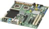
Intel® Workstation Board S5000XVN TPS Fans Feature Server Management Description Support for ƒ Two processor fans ƒ Four front hot-swap fans ƒ Two rear system fans Support for Intel® System Management Software 2.2 Workstation Board Layout Overview Figure 1. Workstation Board Photograph - Intel S5000XVNSATAR | Product Specification - Page 13
Intel® Workstation Board S5000XVN TPS 2.2.1 Workstation Board Connector and Component Layout The following figure shows the board layout of the workstation board Processor 1 socket B. PCI-X 64-bit, 133-/100-MHz fulllength/full-height slot 2 C. PCI Express* x4 (S5000XVNSASR) or x8 (S5000XVNSATAR) - Intel S5000XVNSATAR | Product Specification - Page 14
Intel® Workstation Board S5000XVN TPS Overview H. P12V4 connector I. Back panel I/O ports J. Diagnostic and Identify LEDs K. System fan 6 header L. System fan 5 header W. System fan 2 header X. System fan 1 header Y. Processor power connector Z. USB header AA. IDE connector M. Main power - Intel S5000XVNSATAR | Product Specification - Page 15
Overview 2.2.2 Intel® Workstation Board S5000XVN TPS Workstation Board Mechanical Drawings Figure 3. Mounting Hole Positions 6 Revision 1.5 Intel order number: D66403-006 - Intel S5000XVNSATAR | Product Specification - Page 16
Intel® Workstation Board S5000XVN TPS Overview Figure 4. Component Positions Revision 1.5 7 Intel order number: D66403-006 - Intel S5000XVNSATAR | Product Specification - Page 17
16.05 [ 0.632 ] TYP 11.20 [ 0.441 ] 116.000 [ 4.5669 ] 304.80 [ 12.000 ] 20.32 [ 0.800 ] TYP 60.100 [ 2.3661 ] Intel® Workstation Board S5000XVN TPS IMM3 COMPONENT HEIGHT 3.6 MM HEATSINK DISSASEMBLY AREA, .275" [8.26mm] MAX COMPONENT HEIGHT RESTRICTION, 4 PLACES Ø 10.160 [ 0.4000 ] GROUND PAD - Intel S5000XVNSATAR | Product Specification - Page 18
Intel® Workstation Board S5000XVN TPS 7.620 TYP [ 0.3000 ] 20.320 [ 0.8000 ] 11 PLCS LIMITED COMPONENT HEIGHT .058" MAXIMUM 13 PLACES 3 R 25.40 [ 1.000 ] HOLE LEADS ALLOWED Figure 6. Restricted Areas on Side 2 NO COMPONENTS THIS ZONE 16 PLCS Revision 1.5 9 Intel order number: D66403-006 - Intel S5000XVNSATAR | Product Specification - Page 19
Overview 5.00 [ 0.197 ] 3X 4.00 [ 0.157 ] Intel® Workstation Board S5000XVN TPS 5.00 [ 0.197 ] 3X 3.00 [ 0.118 ] 3X 10.13 [ 0.399 ] CHASSIS ID PADS Figure 7. Restricted Areas on Side 2, "Detail B" 10 Revision 1.5 Intel order number: D66403-006 - Intel S5000XVNSATAR | Product Specification - Page 20
Intel® Workstation Board S5000XVN TPS Overview 188.152 [7.4076 [4.3839] 118.351 [4.6595] 187.152 [7.3682] 194.152 [7.6438] SUPPORT AREA, NO COMPONENT ALLOWED 26.578 [1.0464] 43.302 [1.7048] 16.5mm [4.6398] Figure 8. CPU and Memory Duct Keepout Revision 1.5 11 Intel order number: D66403-006 - Intel S5000XVNSATAR | Product Specification - Page 21
Overview Intel® Workstation Board S5000XVN TPS 2.2.3 Workstation Board ATX I/O Layout The following drawing shows the layout of the rear I/O components for the workstation board: E A B C D F I A. PS/2 mouse B. Serial A port C. NIC 1 (1 Gb) D. NIC 2 E. Audio in H F. Audio out G. - Intel S5000XVNSATAR | Product Specification - Page 22
and design of the Intel® Workstation Board S5000XVN is based on the Intel® S5000X chipset. This chipset is designed for systems that use the Intel® Xeon® processor with system bus speeds of 667 MHz, 1066 MHz, and 1333 MHz. The chipset contains two main components: the Memory Controller Hub (MCH) for - Intel S5000XVNSATAR | Product Specification - Page 23
Architecture Intel® Workstation Board S5000XVN TPS 3.1 Intel® 5000X Memory Controller Hub (MCH) The Memory Controller Hub (MCH) is a single 1432-pin FCBGA package, which includes the following core platform functions: ƒ System Bus Interface for the processor subsystem ƒ Memory Controller - Intel S5000XVNSATAR | Product Specification - Page 24
® Workstation Board S5000XVN TPS Functional Architecture Processor Family Intel® Xeon® Processor 5148 Intel® Xeon® Processor 5150 Intel® Xeon® Processor 5160 Intel® Xeon® Processor E5310 Intel® Xeon® Processor E5320 Intel® Xeon® Processor E5335 Intel® Xeon® Processor E5345 Intel® Xeon® Processor - Intel S5000XVNSATAR | Product Specification - Page 25
Functional Architecture Intel® Workstation Board S5000XVN TPS Figure 11. CEK Processor Mounting 3.1.3 Memory Subsystem The MCH supports four fully buffered DIMM (FBD) memory channels. FBD memory uses a narrow, high-speed, frame-oriented interface referred to as a channel. The four FBD channels - Intel S5000XVNSATAR | Product Specification - Page 26
Intel® Workstation Board S5000XVN TPS Channel B Channel A Functional Architecture Channel C Channel D MCH Branch 0 DIMDMIMDAMIM1DAMIM2DBMIM1DBMIM2DCMIM1DCMIM2DM1D2 Branch 1 TP02299 Figure 12. Memory Layout To boot the system, the system BIOS on the workstation board uses a dedicated I2C bus to - Intel S5000XVNSATAR | Product Specification - Page 27
Functional Architecture Intel® Workstation Board S5000XVN TPS 3.1.3.1 Memory RASUM Features The MCH supports several memory RASUM (Reliability, Availability, Serviceability, Usability, and Manageability) features. These features include the Intel® x4 Single Device Data Correction (Intel® x4 SDDC - Intel S5000XVNSATAR | Product Specification - Page 28
® Workstation Board S5000XVN TPS Functional Architecture Note: This workstation board supports only fully buffered DDR2 DIMMs (FBDIMMs. See the Intel® Workstation Board S5000XVN Tested Memory List for a list of supported memory for this server board. 3.1.3.3 DIMM Population Rules and Supported - Intel S5000XVNSATAR | Product Specification - Page 29
Intel® Workstation Board S5000XVN TPS In the following table, the following codes are used: ƒ VP: Validated configuration and the slot is populated ƒ SP: Supported is only tested and supported with a 512 MB x8 FBDIMM installed in DIMM Socket A1. The supported memory configurations must meet - Intel S5000XVNSATAR | Product Specification - Page 30
0 DIMDMIMDAMIM1DAMIM2DBMIM1DBMIM2DCMIM1DCMIM2DM1D2 Branch 1 TP02300 Figure 13. Minimum 2-DIMM Memory Configuration Note: The workstation board supports single DIMM mode operation. Intel will only validate and support this configuration with a single 512 MB x8 FBDIMM installed in DIMM socket A1 - Intel S5000XVNSATAR | Product Specification - Page 31
Fuctional Architecture Intel® Workstation Board S5000XVN TPS Channel B Channel A Channel C Channel D MCH of memory and is not supported across branches. There are two supported memory sparing configurations. ƒ Single Branch Mode Sparing ƒ Dual Branch Mode Sparing 22 Revision 1.5 Intel order - Intel S5000XVNSATAR | Product Specification - Page 32
Intel® Workstation Board S5000XVN TPS 3.1.3.4.2.1 Single Branch Mode Sparing Slot 2 DIMM_A2 Slot 1 DIMM_A1 DIMM_B2 DIMM_B1 Channel A Channel B Branch 0 Functional Architecture DIMM_C2 DIMM_C1 DIMM_D2 DIMM_D1 Channel C Channel D Branch 1 Intel® 5000X Memory Dual Branch Mode Sparing Dual - Intel S5000XVNSATAR | Product Specification - Page 33
Intel® Workstation Board S5000XVN TPS 3.1.4 Snoop Filter The 5000X version of the MCH includes a snoop filter. Depending on the application of the workstation, you can use this feature to enhance the performance of the workstation by eliminating traffic on the snooped system bus of the processor - Intel S5000XVNSATAR | Product Specification - Page 34
PCI32 segment. The PCI32 segment is not connected to any devices on the workstation board S5000XVN. 3.2.1.2 PXA: 64-bit, 133-MHz PCI Subsystem One 64-bit PCI-X bus segment for workstation boards that do not support SAS by combining PE2 with PE1. Revision 1.5 25 Intel order number: D66403-006 - Intel S5000XVNSATAR | Product Specification - Page 35
enable/disable and/or configure the SATA ports by accessing the BIOS Setup utility during POST. 3.2.2.1 Intel® Embedded Server RAID Technology II Support The onboard storage capability of this workstation board includes support for Intel® Embedded Server RAID Technology II, which provides three - Intel S5000XVNSATAR | Product Specification - Page 36
Intel® Workstation Board S5000XVN TPS Functional Architecture For higher performance, you can use data stripping to alleviate disk bottlenecks by taking advantage of the dual independent DMA engines that each SATA port offers. Data mirroring is used for data security. If a disk fails, a mirrored - Intel S5000XVNSATAR | Product Specification - Page 37
Architecture Intel® Workstation Board S5000XVN TPS 3.3 Audio Codec The workstation board supports the Intel® High Definition audio subsystem based on the Realtek* ALC260 audio codec. The ALC260 is a 2-channel HD Audio codec featuring a 24-bit, 2-channel DAC and two stereo 20-bit ADCs. ESB2 Intel - Intel S5000XVNSATAR | Product Specification - Page 38
for SAS functionality. For SATA workstation boards, all six SATA connectors are used for SATA functionality. 3.5 Network Interface Controller (NIC) Network interface support is provided from the built in Dual GbE MAC features of the ESB2 in conjunction with the Intel® 82563EB compact Physical Layer - Intel S5000XVNSATAR | Product Specification - Page 39
. Intel I/OAT improves network application responsiveness by using the power of Intel® Xeon® processors 5000 support risks of third-party network stacks and preserving existing network requirements, such as teaming and failover. 3.5.2 MAC Address Definition Each Intel® Workstation Board S5000XVN - Intel S5000XVNSATAR | Product Specification - Page 40
the workstation board for keyboard and mouse support. Either port can support a mouse or keyboard. Neither port supports hot plugging. 3.6.4 Wake-up Control The super I/O contains functionality that allows various events to power on and power off the system. Revision 1.5 31 Intel order number - Intel S5000XVNSATAR | Product Specification - Page 41
Functional Architecture Intel® Workstation Board S5000XVN TPS 3.6.5 System Health Support The super I/O provides an interface via GPIOs for BIOS and system management firmware to activate the diagnostic LEDs, the FRU fault indicator LEDs for processors, FBDIMMS, fans, and the system status LED. - Intel S5000XVNSATAR | Product Specification - Page 42
Intel® Workstation Board S5000XVN TPS Platform Management 4. Platform Management The platform management subsystem is based on the integrated Baseboard Management Controller features of the ESB2-E. The onboard platform management - Intel S5000XVNSATAR | Product Specification - Page 43
Platform Management Intel® Workstation Board S5000XVN TPS Figure 18. SMBUS Block Diagram 34 Revision 1.5 Intel order number: D66403-006 - Intel S5000XVNSATAR | Product Specification - Page 44
reference designators printed on the silkscreen: Table 11. Board Connector Matrix Connector Quantity Reference Designators Connector Type Pin Count Power supply 4 CPU 2 Main memory 8 PCI-X 2 PCI Express* x8 2 PCI Express* x16 1 RAID Key 2 IDE 1 System fans 4 System fans - Intel S5000XVNSATAR | Product Specification - Page 45
-outs Intel® Workstation Board S5000XVN TPS Connector Configuration jumpers Quantity Reference Designators Connector Type Pin Count 4 J1D2 (Password Clear), J1D1 (CMOS Clear), J1C3 Jumper 3 (BIOS Bank Select), J1E3 (BMC Force Update) 5.2 Power Connectors The main power supply connection - Intel S5000XVNSATAR | Product Specification - Page 46
Intel® Workstation Board S5000XVN TPS Connector/Header Locations and Pin-outs Table 13. 12-V Power Connector Pin-out (J3J2) Pin Signal Color 1 GND Black 2 GND Black 3 GND Black 4 GND Black 5 +12 Vdc Yellow/black 6 +12 Vdc Yellow/black 7 +12 Vdc - Intel S5000XVNSATAR | Product Specification - Page 47
Connector/Header Locations and Pin-outs Intel® Workstation Board S5000XVN TPS 5.3.2 5.3.3 5.3.4 5.3.5 5.3.6 IPMB Header Table 17. IPMB Header Pin-out (J4J1) Pin Signal Name 1 SMB_IPMB_5VSB_DAT 2 GND 3 SMB_IPMB_5VSB_CLK HSBP Header Description BMC IMB 5 V Standby Data Line Ground - Intel S5000XVNSATAR | Product Specification - Page 48
Intel® Workstation Board S5000XVN TPS Connector/Header Locations and Pin-outs 5.4 Front Panel Connector The workstation board provides a 24-pin SSI front panel connector (J1E4) for use with Intel FP_PWR_BTN_N Power Button 12 NIC1_ACT_LED_N NIC 1 Activity LED - 13 GND (Power Button GND) Power - Intel S5000XVNSATAR | Product Specification - Page 49
and Pin-outs Intel® Workstation Board S5000XVN TPS Pin 7 8 9 10 11 (D1) 12 (D2) 13 (D3) 14 15 16 Signal Name NIC_A_MDI1P NIC_A_MDI1N NIC_A_MDI0P NIC_A_MDI0N NIC_LINKA_1000_N (LED NIC_LINKA_100_N (LED) NIC_ACT_LED_N NIC_LINK_LED_N GND GND 5.5.2 IDE Connector The workstation board provides one - Intel S5000XVNSATAR | Product Specification - Page 50
Intel® Workstation Board S5000XVN TPS Connector/Header Locations and Pin-outs 5.5.3 SATA/SAS Connectors The workstation board provides up to six SATA/SAS connectors: ƒ SATA-0 (J1J1) ƒ SATA-1 (J1H2) ƒ SATA-2/SAS-0 (J1H1) ƒ SATA-3/SAS-1 (J1G2) ƒ SATA-4/SAS-2 (J1G1) ƒ SATA-5/SAS-3 (J1F2) The pin - Intel S5000XVNSATAR | Product Specification - Page 51
Locations and Pin-outs Intel® Workstation Board S5000XVN TPS Table 27. stacked PS/2* ports (J9A1) support a keyboard and a mouse. Either PS/2 port can support a mouse or keyboard. The power Keyboard clock Test point - keyboard/mouse Mouse data Test point - keyboard/mouse Ground Keyboard/mouse power - Intel S5000XVNSATAR | Product Specification - Page 52
Intel® Workstation Board S5000XVN TPS Connector/Header support an additional two USB ports. The pin-out of the connector is detailed in the following table: Table 30. Internal USB Connector Pin-out (J3J1) Pin Signal Name Description 1 USB2_VBUS5 USB power (port 5) 2 USB2_VBUS4 USB power - Intel S5000XVNSATAR | Product Specification - Page 53
Intel® Workstation Board S5000XVN TPS 5.6 Fan Headers The workstation board provides four SSI-compliant 4-pin and four SSI-compliant 6-pin fan headers to be used as CPU, and I/O cooling fans. 3-pin fans are supported GND Power In Out Description Ground is the power supply ground Power supply 12 - Intel S5000XVNSATAR | Product Specification - Page 54
Intel® Workstation Board S5000XVN TPS Connector/Header Locations and Pin-outs Note: Intel Corporation workstation boards support peripheral components and contain a number of high-density VLSI and power delivery components that need adequate airflow to cool. Intel's own chassis are designed and - Intel S5000XVNSATAR | Product Specification - Page 55
Intel® Workstation Board S5000XVN TPS 6. Jumper Blocks The workstation board has several 3-pin jumper blocks that you can use to configure, protect, or recover specific features of the server board settings are cleared immediately upon removal of AC power. These pins should not be jumpered for - Intel S5000XVNSATAR | Product Specification - Page 56
Intel® Workstation Board S5000XVN TPS Jumper Blocks 6.1 CMOS Clear and Password Reset Usage Procedure previous generation Intel server boards. The following procedure outlines the new usage model. 1. Power down server. Do not unplug the power cord. 2. Open the server chassis. For instructions, see - Intel S5000XVNSATAR | Product Specification - Page 57
Intel® Workstation Board S5000XVN TPS 7. Power down and remove the AC power cord. 8. Open the server chassis. 9. Move jumper from the enabled position, covering pins 2 and 3 to the disabled position, covering pins 1 and 2. 10. Close the server chassis. 11. Reconnect the AC cord and power supported - Intel S5000XVNSATAR | Product Specification - Page 58
Intel® Workstation Board S5000XVN TPS Intel® Light Guided Diagnostics 7. Intel® Light Guided Diagnostics The workstation boards have several onboard diagnostic LEDs to assist in troubleshooting board-level issues. This section provides a description the location and function of each LED on the - Intel S5000XVNSATAR | Product Specification - Page 59
Intel® Light Guided Diagnostics Intel® Workstation Board S5000XVN TPS 7.2 Fan Fault LEDs Fan fault LEDs are present for the two CPU fans and the two rear system fans. The two CPU fan fault LEDs are located next to each CPU fan header. The two rear system fan fault LEDs are located next to each - Intel S5000XVNSATAR | Product Specification - Page 60
Intel® Workstation Board S5000XVN TPS Intel® Light Guided Diagnostics 7.3 System ID LED and System Status LED The workstation board provides LEDs for both system ID and system status. These LEDs are located in the rear I/O area of the workstation board between the PS/2* mouse/keyboard stacked - Intel S5000XVNSATAR | Product Specification - Page 61
up. ƒ In mirrored configuration, when memory mirroring takes place and system loses memory redundancy. ƒ Redundancy loss such as power-supply or fan. This does not apply to non-redundant subsystems. ƒ PCI Express* link errors ƒ CPU failure/disabled - if there are two processors and one of them fails - Intel S5000XVNSATAR | Product Specification - Page 62
Intel® Workstation Board S5000XVN TPS Intel® Light Guided Diagnostics 7.3.1 System Status LED - BMC Initialization When the AC power is first applied to the system and 5V-STBY is present, the BMC on the server board requires 20-30 seconds to initialize. During this time, the system status LED - Intel S5000XVNSATAR | Product Specification - Page 63
Intel® Light Guided Diagnostics Intel® Workstation Board S5000XVN TPS 7.5 Processor Fault LEDs The workstation board provides a fault LED for each processor socket. These LEDs are located near the processor sockets. AF001035 Figure 24. Processor Fault LED Locations 7.6 Post Code Diagnostic LEDs - Intel S5000XVNSATAR | Product Specification - Page 64
Intel® Workstation Board S5000XVN TPS Intel® Light Guided Diagnostics B A A. Status LED B. ID LED C. MSB LED (POST LED) DF CE D. Bit 2 LED (POST LED) E. Bit 1 LED (POST LED) F. LSB LED (POST LED) Figure 25. POST Code Diagnostic LED Location AF001036 Revision 1.5 55 Intel order number: - Intel S5000XVNSATAR | Product Specification - Page 65
: 1 Chassis design must provide proper airflow to avoid exceeding the Dual-Core Intel® Xeon® processor 5000 sequence maximum case temperature. Disclaimer Note: Intel Corporation workstation boards contain a number of high-density VLSI and power delivery components that need adequate airflow to cool - Intel S5000XVNSATAR | Product Specification - Page 66
of operation based on statistical regression. 8.3 Workstation Board Power Requirements This section provides power supply design guidelines for a system using the Intel® Workstation Board S5000XVN including voltage and current specifications, and power supply on/off sequencing characteristics. The - Intel S5000XVNSATAR | Product Specification - Page 67
Design and Environmental Specifications Intel® Workstation Board S5000XVN TPS Figure 26. Power Distribution Block Diagram 58 Revision 1.5 Intel order number: D66403-006 - Intel S5000XVNSATAR | Product Specification - Page 68
Intel® Workstation Board S5000XVN TPS Design and Environmental Specifications 8.3.1 Processor Power Support The workstation board supports the Thermal Design Point (TDP) guideline for Intel® Xeon® processors. The Flexible Motherboard Guidelines (FMB) also were followed to help determine the - Intel S5000XVNSATAR | Product Specification - Page 69
Design and Environmental Specifications Intel® Workstation Board S5000XVN TPS 8.4.1 Grounding The grounds of the pins of the power supply output connector provide the power return path. The output connector ground pins is connected to safety ground (power supply enclosure). This grounding should - Intel S5000XVNSATAR | Product Specification - Page 70
Intel® Workstation Board S5000XVN TPS Design and Environmental Specifications Parameter Table 39. Voltage Regulation 8.4.6 Capacitive Loading The power supply shall be stable and meet all requirements with the following capacitive loading ranges. Revision 1.5 61 Intel order number: D66403-006 - Intel S5000XVNSATAR | Product Specification - Page 71
Specifications Intel® Workstation Board S5000XVN TPS Table 41. Capacitive Loading Conditions Output Minimum Maximum Units +3.3 V 250 6800 F +5 V 400 4700 F +12 V 1, 2, 3, 4 500 each 11,000 F -12 V 1 350 F +5 VSB 20 350 F Note: 1. Maximum continuous total output power should - Intel S5000XVNSATAR | Product Specification - Page 72
Intel® Workstation Board S5000XVN TPS Design and Environmental Specifications Table 42. Ripple and Noise +3.3 V 50mVp-p +5 V 50mVp-p +12 V 1, 2, 3, 4 120mVp-p -12 V 120mVp-p +5 VSB 50mVp-p Note: 1. 2. 3. 4. Maximum continuous total output power requirements for the power supply being turned - Intel S5000XVNSATAR | Product Specification - Page 73
Design and Environmental Specifications V out Intel® Workstation Board S5000XVN TPS 10% V out V1 V2 V3 V4 Tvout_rise Tvout_on Tvout_off Figure 27. Output Voltage Timing TP02313 Table 44. 400 50 500 1000 Units ms ms ms ms ms ms ms ms ms ms ms 64 Revision 1.5 Intel order number: D66403-006 - Intel S5000XVNSATAR | Product Specification - Page 74
Intel® Workstation Board S5000XVN TPS AC Input Vout TAC_on_delay Tsb_on_delay PWOK Tpwok_on and all outputs simultaneously. It also should not trip the power supply protection circuits during turn on. Residual voltage at the power supply outputs for a no load condition shall not exceed 100 - Intel S5000XVNSATAR | Product Specification - Page 75
Regulatory and Certification Information Intel® Workstation Board S5000XVN TPS 9. Regulatory and Certification Information To help ensure EMC compliance with your local regional rules and regulations, before computer integration, make sure that the chassis, power supply, and other modules have - Intel S5000XVNSATAR | Product Specification - Page 76
Intel® Workstation Board S5000XVN TPS Regulatory and Certification Information 9.1.3 Certifications/Registrations/Declarations ƒ UL Declaration (International) 9.2 Product Regulatory Compliance Markings The Intel® Server Board bears the following regulatory marks: Regulatory Compliance UL Mark - Intel S5000XVNSATAR | Product Specification - Page 77
Certification Information Intel® Workstation Board S5000XVN TPS including interference that may cause undesired operation. Intel Corporation 5200 N.E. Elam Young Parkway Hillsboro, OR installed and used in accordance with the instructions, may cause harmful interference to radio communications - Intel S5000XVNSATAR | Product Specification - Page 78
Intel® Workstation Board S5000XVN and use the equipment according to the instruction manual. 9.3.5 BSMI (Taiwan) The BSMI Intel representative 3. Name of Certification Recipient: Intel Corporation 4. Date of Manufacturer: Refer to date code on product 5. Manufacturer/Nation: Intel Corporation - Intel S5000XVNSATAR | Product Specification - Page 79
Regulatory and Certification Information Intel® Workstation Board S5000XVN TPS 9.4 Restriction of Hazardous Substances (RoHS) Compliance Intel has a system in place to restrict the use of banned substances in accordance with the European Directive 2002/95/EC. Compliance is based on declaration - Intel S5000XVNSATAR | Product Specification - Page 80
S5000PSL, S5000XSL, S5000XVN, and Server System SC5400RA Tested Hardware and OS List. ƒ For a list of Intel supported hard disk drives for this workstation board, see the Intel® Server Board/Systems Tested Hard Drive List. ƒ This workstation board supports only Intel® Xeon® processors 5000 sequence - Intel S5000XVNSATAR | Product Specification - Page 81
Appendix B: BMC Sensor Tables Intel® Workstation Board S5000XVN TPS Appendix B: BMC Sensor Tables This appendix lists the sensor identification numbers and information about the sensor type, name, supported thresholds, assertion and de-assertion information, and a brief description of the sensor - Intel S5000XVNSATAR | Product Specification - Page 82
Intel® Workstation Board S5000XVN TPS Appendix B: BMC Sensor Tables ƒ Rearm Sensors The rearm is a request for the event status for a sensor to be rechecked and updated upon a transition between good and bad states. Rearming the sensors can be done manually or automatically. This column indicates - Intel S5000XVNSATAR | Product Specification - Page 83
Appendix B: BMC Sensor Tables Intel® Workstation Board S5000XVN TPS Table 45. BMC Sensors Sensor Name Power Unit Status Sensor Number 01h Power Unit 02h Redundancy Watchdog 03h System Applicability All Chassisspecific All Sensor Type Power Unit 09h Event/Reading Type Sensor Specific 6Fh - Intel S5000XVNSATAR | Product Specification - Page 84
Intel® Workstation Board S5000XVN TPS Appendix B: BMC Sensor Tables Sensor Name Platform Security Violation Sensor Number 04h Physical 05h Security FP Diag 07h Interrupt (NMI) System 09h Event Log Session 0Ah Audit System 0Bh Event ('System Event') BB +1.2V 10h Vtt BB+1.9V 11h NIC Core BB +1. - Intel S5000XVNSATAR | Product Specification - Page 85
Appendix B: BMC Sensor Tables Intel® Workstation Board S5000XVN TPS Sensor Name BB +3.3V Sensor Number 15h BB +3.3V 16h STB BB +1.5V 17h ESB BB +5V 18h BB +1.2V 19h NIC BB +12V 1Ah AUX BB 0.9V 1Bh BB Vbat 1Eh BB Temp 30h Front 32h Panel Temp BNB Temp 33h CPU 1 50h FAN CPU 2 51h FAN - Intel S5000XVNSATAR | Product Specification - Page 86
Intel® Workstation Board S5000XVN TPS Appendix B: BMC Sensor Tables Sensor Name SYS FAN 2 TACH SYS FAN 3 TACH' SYS FAN 4 TACH and - T De OK As and - T De OK As and - T De OK As and - T De A - A - A - A - A - A - A - Revision 1.5 77 Intel order number: D66403-006 - Intel S5000XVNSATAR | Product Specification - Page 87
Appendix B: BMC Sensor Tables Intel® Workstation Board S5000XVN TPS Sensor Name Fan 8 Present Fan 9 Present Fan 10 Present Fan Redundancy Power Supply Status 1 Power Supply Status 2 Sensor Number 67h 68h 69h 6Fh 70h 71h System Applicability Chassisspecific Chassisspecific Chassisspecific - Intel S5000XVNSATAR | Product Specification - Page 88
Intel® Workstation Board S5000XVN TPS Appendix B: BMC Sensor Tables Sensor Name Power Nozzle Sensor Number 78h Power Supply 1 Power 79h Nozzle Power Supply 2 Power 7Ah Gauge V1 rail (+12v) Power Supply 1 Power 7Bh Gauge V1 rail (+12v) Power Supply 2 Power 7Ch Gauge (aggre- - Intel S5000XVNSATAR | Product Specification - Page 89
Appendix B: BMC Sensor Tables Intel® Workstation Board S5000XVN TPS Sensor Name System ACPI Power State Sensor Number 82h Button 84h asserted 03h OEM Digital 01h - State OK C0h Discrete asserted 03h Processor 07h Sensor Specific 6Fh IERR Thermal trip Config error Critical Non-rec - Intel S5000XVNSATAR | Product Specification - Page 90
Intel® Workstation Board S5000XVN TPS Appendix B: BMC Sensor Tables Sensor Name Proc 1 Temp Sensor Number 98h Proc 2 9Ah Temp PCIe Link0 See the BIOS EPS As - See the BIOS EPS As - See the BIOS EPS Rearm A A A A A A A A A Standby Revision 1.5 81 Intel order number: D66403-006 - Intel S5000XVNSATAR | Product Specification - Page 91
Appendix B: BMC Sensor Tables Intel® Workstation Board S5000XVN TPS Sensor Sensor Name Number PCIe Link7 A7h PCIe Link8 A8h PCIe Link9 A9h PCIe As and Analog De As and Analog De Trig Offset Trig Offset Rearm A A A A A A A M M Standby 82 Revision 1.5 Intel order number: D66403-006 - Intel S5000XVNSATAR | Product Specification - Page 92
Intel® Workstation Board S5000XVN TPS Appendix B: BMC Sensor Tables Sensor Name Proc 1 VRD Over Temp Sensor Number C8h Proc 2 C9h VRD Over Temp Proc 1 Vcc D0h Proc 2 Vcc D1h Proc 1 Vcc D2h Out-ofRange Proc 2 D3h Vcc Outof-Range CPU 01h - Limit exceeded Processor Generic 07h 03h 01h - Intel S5000XVNSATAR | Product Specification - Page 93
Appendix B: BMC Sensor Tables Intel® Workstation Board S5000XVN TPS Sensor Name DIMM B2 DIMM C1 DIMM C2 DIMM D1 DIMM D2 Memory A Error Memory B Error Sensor Number E3h E4h E5h E6h E7h ECh EDh System Applicability All All All All All All Systemspecific Sensor Type Event/Reading Event Offset - Intel S5000XVNSATAR | Product Specification - Page 94
Intel® Workstation Board S5000XVN TPS Appendix B: BMC Sensor Tables Sensor Name Memory C Error Sensor Number EEh Memory D EFh res Non-red: insuff res Entity Sensor Presence Specific Entity present 25h 6Fh Memory Discrete 0Bh Fully redundant 0Ch Non-red:suff res from redund Non-red: - Intel S5000XVNSATAR | Product Specification - Page 95
Appendix B: BMC Sensor Tables Intel® Workstation Board S5000XVN TPS Sensor Name Sensor Number System Applicability Sensor Type Event/Reading Type Event Offset Triggers Non-red: insuff res Note 1: Not supported except for ESB2 embedded NICs. Criticality Crtical Assert/ Readable Event Data - Intel S5000XVNSATAR | Product Specification - Page 96
Intel® Workstation Board S5000XVN TPS Appendix C: POST Code Diagnostic LED Decoder Appendix C: POST Code the POST code to the POST Code Diagnostic LEDs on the back edge of the workstation board. To assist in troubleshooting a system hang during the POST process, you can use the Diagnostic LEDs to - Intel S5000XVNSATAR | Product Specification - Page 97
Appendix C: POST Code Diagnostic LED Decoder Intel® Workstation Board S5000XVN TPS Table 47. Diagnostic LED POST Code Decoder Checkpoint Host Processor Diagnostic LED Decoder G=Green, R=Red, A=Amber MSB Bit 2 Bit 1 LSB 0x10h Off Off Off R 0x11h Off Off Off A 0x12h Off Off G R 0x13h - Intel S5000XVNSATAR | Product Specification - Page 98
Intel® Workstation Board S5000XVN TPS Appendix C: POST Code Diagnostic LED Core 0xE0h R R R Off Description Enabling the console controller Resetting the keyboard Disabling the keyboard Detecting the presence of the keyboard Enabling the keyboard Clearing keyboard input buffer Instructing - Intel S5000XVNSATAR | Product Specification - Page 99
Intel® Workstation Board S5000XVN TPS Checkpoint 0xE2h Diagnostic LED Decoder G=Green, R=Red, A=Amber MSB Bit 2 Bit 1 LSB R R A Off 0xE1h R R R G 0xE3h R R A G Driver Execution Environment (DXE) Core G G A A Description Initial memory found, configured, and installed correctly - Intel S5000XVNSATAR | Product Specification - Page 100
Intel® Workstation Board S5000XVN memory to shadow PCI ROM Processor 01 internal error (IERR) on last boot Processor 02 internal error (IERR) on last boot Processor 01 thermal trip error on last boot Processor 02 thermal trip error on last boot Processor 01 disabled Processor 02 disabled Processor - Intel S5000XVNSATAR | Product Specification - Page 101
Appendix D: POST Code Errors Intel® Workstation Board S5000XVN TPS Error Code 8305 84F2 84F3 84F4 84FF 8500 8520 Baseboard management controller in update mode Sensor data record empty System event log full Memory Component could not be configured in the selected RAS mode. DIMM_A1 failed Self Test - Intel S5000XVNSATAR | Product Specification - Page 102
fault: DC power unexpectedly lost (power good dropout) Chipset control failure Power control fault CPU Population Error N/A N/A N/A Power Unit - power unit failure offset N/A Power Unit - soft power control failure offset Supported? Yes No No No Yes No Yes Revision 1.5 93 Intel order number - Intel S5000XVNSATAR | Product Specification - Page 103
Appendix E: Supported Intel® Server Chassis Intel® Workstation Board S5000XVN TPS Appendix E: Supported Intel® Server Chassis The Intel® Workstation Board S5000XVN is supported in the following Intel® pedestal server chassis: ƒ Intel® Server Chassis SC5400 BASE ƒ Intel® Entry Server Chassis SC5299 - Intel S5000XVNSATAR | Product Specification - Page 104
Intel® Workstation Board S5000XVN TPS MB FRB FRU FSB GB GPIO GTL HSC Hz I2C IA IBF ICH IC MB Definition Advanced Configuration and Power Interface Application Processor memory, which normally resides on the server board. Direct Platform Control Electrically Erasable Programmable Read-Only Memory - Intel S5000XVNSATAR | Product Specification - Page 105
-On Self Test Power Supply Management Interface Pulse-Width Modulation Random Access Memory Reliability, Availability, Serviceability, Usability, and Manageability Reduced Instruction Set Computing Read Only Memory Real-Time Clock (Component of ICH peripheral chip on the server board) Sensor Data - Intel S5000XVNSATAR | Product Specification - Page 106
Intel® Workstation Board S5000XVN TPS Term SEL SIO SMI SMM SMS SNMP TBD TIM UART UDP UHCI UTC VID VRD Word ZIF Interface Universal time coordinare Voltage Identification Voltage Regulator Down 16-bit quantity Zero Insertion Force Glossary Revision 1.5 97 Intel order number: D66403-006 - Intel S5000XVNSATAR | Product Specification - Page 107
Reference Documents Intel® Workstation Board S5000XVN TPS Reference Documents For additional information, refer to the following documents: ƒ Intel® S5000 Server Board Family Datasheet ƒ Intel 5000 Series Chipset Memory Controller Hub Datasheet ƒ Intel 631xESB/632xESB I/O Controller Hub Datasheet
-
 1
1 -
 2
2 -
 3
3 -
 4
4 -
 5
5 -
 6
6 -
 7
7 -
8
-
9
-
10
-
11
-
12
-
13
-
14
-
15
-
16
-
17
-
18
-
19
-
20
-
21
-
22
-
23
-
24
-
25
-
26
-
27
-
28
-
29
-
30
-
31
-
32
-
33
-
34
-
35
-
36
-
37
-
38
-
39
-
40
-
41
-
42
-
43
-
44
-
45
-
46
-
47
-
48
-
49
-
50
-
51
-
52
-
53
-
54
-
55
-
56
-
57
-
58
-
59
-
60
-
61
-
62
-
63
-
64
-
65
-
66
-
67
-
68
-
69
-
70
-
71
-
72
-
73
-
74
-
75
-
76
-
77
-
78
-
79
-
80
-
81
-
82
-
83
-
84
-
85
-
86
-
87
-
88
-
89
-
90
-
91
-
92
-
93
-
94
-
95
-
96
-
97
-
98
-
99
-
100
-
101
-
102
-
103
-
104
-
105
-
106
-
107
 |
 |

Intel
®
Workstation Board S5000XVN
Technical Product Specification
Intel order number: D66403-006
Revision 1.5
August 2010
Enterprise Platforms and Services Division – Marketing