Intel S5000XVNSATAR Product Specification - Page 13
Workstation Board Connector and Component Layout
 |
View all Intel S5000XVNSATAR manuals
Add to My Manuals
Save this manual to your list of manuals |
Page 13 highlights
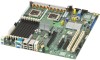
Overview Intel® Workstation Board S5000XVN TPS 2.2.1 Workstation Board Connector and Component Layout The following figure shows the board layout of the workstation board. Each connector and major component is identified by a letter. A component descriptions table follows the figure. G A B C D EF H I J RR QQ PP OO NN MM LL KK JJ II HH GG FF EE DD BB Z X V T CC AA Y W U A. PCI-X* 64-bit, 100-MHz fulllength/full-height slot 1 P. Processor 1 socket B. PCI-X 64-bit, 133-/100-MHz fulllength/full-height slot 2 C. PCI Express* x4 (S5000XVNSASR) or x8 (S5000XVNSATAR) full-length/fullheight slot 3 (x8 connector) D. PCI Express* x4 half-length/fullheight slot 4 (x8 connector) E. CMOS battery Q. Processor 2 socket R. Processor 2 fan header S. Processor 1 fan header T. System fan 4 header F. PCI Express x16 full-length/fullheight slot 6 (x16 connector) G. CD-ROM line-in connector U. System fan 3 header V. IPMB connector K L M N O P Q R S AF000499 EE. Enclosure management SAS SES I2C (order code S5000XVNSASR only) FF. Hot-swap backplane A header GG. SATA 0 HH. SATA 1 II. SATA 2 or SAS 0 (SAS 0 on order code S5000XVNSASR only) JJ. SATA 3 or SAS 1 (SAS 1 on order code S5000XVNSASR only) KK. SATA 4 or SAS 2 (SAS 2 on order code S5000XVNSASR only) 4 Revision 1.5 Intel order number: D66403-006
-
 1
1 -
2
-
3
-
4
-
5
-
6
-
7
-
 8
8 -
 9
9 -
 10
10 -
 11
11 -
 12
12 -
 13
13 -
 14
14 -
 15
15 -
 16
16 -
 17
17 -
 18
18 -
19
-
20
-
21
-
22
-
23
-
24
-
25
-
26
-
27
-
28
-
29
-
30
-
31
-
32
-
33
-
34
-
35
-
36
-
37
-
38
-
39
-
40
-
41
-
42
-
43
-
44
-
45
-
46
-
47
-
48
-
49
-
50
-
51
-
52
-
53
-
54
-
55
-
56
-
57
-
58
-
59
-
60
-
61
-
62
-
63
-
64
-
65
-
66
-
67
-
68
-
69
-
70
-
71
-
72
-
73
-
74
-
75
-
76
-
77
-
78
-
79
-
80
-
81
-
82
-
83
-
84
-
85
-
86
-
87
-
88
-
89
-
90
-
91
-
92
-
93
-
94
-
95
-
96
-
97
-
98
-
99
-
100
-
101
-
102
-
103
-
104
-
105
-
106
-
107
 |
 |
