Intel S5500BCR Service Guide - Page 20
RAID Support - bios
 |
View all Intel S5500BCR manuals
Add to My Manuals
Save this manual to your list of manuals |
Page 20 highlights
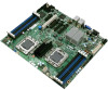
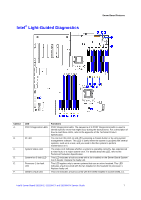
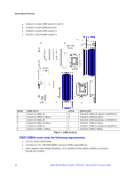
Server Board Features Callout LED G. DIMM C2 fault LED H. DIMM B1 fault LED I. DIMM B2 fault LED J. DIMM A1 fault LED K. DIMM A2 fault LED L. Processor 2 fan fault LED M. DIMM D2 fault LED (Empty in S5500HCV) N. DIMM D1 fault LED O. DIMM E2 fault LED (Empty in S5500HCV) P. DIMM E1 fault LED Q. DIMM F2 fault LED (Empty in S5500HCV) R. DIMM F1 fault LED S. +5-V Standby LED Functions Replace the faulty DIMM. This LED indicates a fault occurred with the DIMM installed in socket DIMM_C2. Replace the faulty DIMM. This LED indicates a fault occurred with the DIMM installed in socket DIMM_B1. Replace the faulty DIMM. This LED indicates a fault occurred with the DIMM installed in socket DIMM_B2. Replace the faulty DIMM. This LED indicates a fault occurred with the DIMM installed in socket DIMM_A1. Replace the faulty DIMM. This LED indicates a fault occurred with the DIMM installed in socket DIMM_A2. Replace the faulty DIMM. This LED applies only to server systems that use an active heatsink. This LED indicates a fault occurred with a fan installed on the heatsink for processor 2. Replace faulty unit. This LED indicates a fault occurred with the DIMM installed in socket DIMM_D2. Replace the faulty DIMM. This LED indicates a fault occurred with the DIMM installed in socket DIMM_D1. Replace the faulty DIMM. This LED indicates a fault has occurred with the DIMM installed in socket DIMM_E2. Replace the faulty DIMM. This LED indicates a fault occurred with the DIMM installed in socket DIMM_E1. Replace the faulty DIMM. This LED indicates a fault occurred with the DIMM installed in socket DIMM_F2. Replace the faulty DIMM. This LED indicates a fault occurred with the DIMM installed in socket DIMM_F1. Replace the faulty DIMM. This LED is green whenever AC power is applied to the system. You do not need to power on the system for this LED to be on. Figure 6. Intel® Light-Guided Diagnostics RAID Support The Intel® Server Board S5520HC/S5500HCV provide an embedded SATA controller that supports both 1.5 Gbps and 3.0 Gbps data transfer rates. The BIOS Setup Utility provides drive configuration options on the Advanced | Mass Storage Controller Configuration setup page, some of which affect the ability to configure RAID. The "On-board SATA Controller" option is enabled by default and when enabled, you can set the "SATA Mode" option to either one of the following four modes: „ "Enhanced" - Enhanced Mode supports up to six SATA ports with IDE native Mode. „ "Compatibility" - Supports up to four SATA ports [0/1/2/3] with IDE Legacy mode and two SATA ports [4/5] with IDE Native Mode. „ "AHCI" - Supports all SATA ports using the Advanced Host Controller Interface. „ "SW RAID" - Intel® Embedded Server RAID Technology II is enabled by "SW RAID" mode. The Intel® Embedded Server RAID Technology II feature provides RAID modes 0, 1, and 10. 8 Intel® Server Board S5520HC, S5520HCT and S5500HCV Service Guide
-
 1
1 -
2
-
3
-
4
-
5
-
6
-
7
-
8
-
9
-
10
-
11
-
12
-
13
-
14
-
 15
15 -
 16
16 -
 17
17 -
 18
18 -
 19
19 -
 20
20 -
 21
21 -
 22
22 -
 23
23 -
 24
24 -
 25
25 -
26
-
27
-
28
-
29
-
30
-
31
-
32
-
33
-
34
-
35
-
36
-
37
-
38
-
39
-
40
-
41
-
42
-
43
-
44
-
45
-
46
-
47
-
48
-
49
-
50
-
51
-
52
-
53
-
54
-
55
-
56
-
57
-
58
-
59
-
60
-
61
-
62
-
63
-
64
-
65
-
66
 |
 |
