Intel S5520HCT Product Specification - Page 132
Jumper Blocks
 |
View all Intel S5520HCT manuals
Add to My Manuals
Save this manual to your list of manuals |
Page 132 highlights
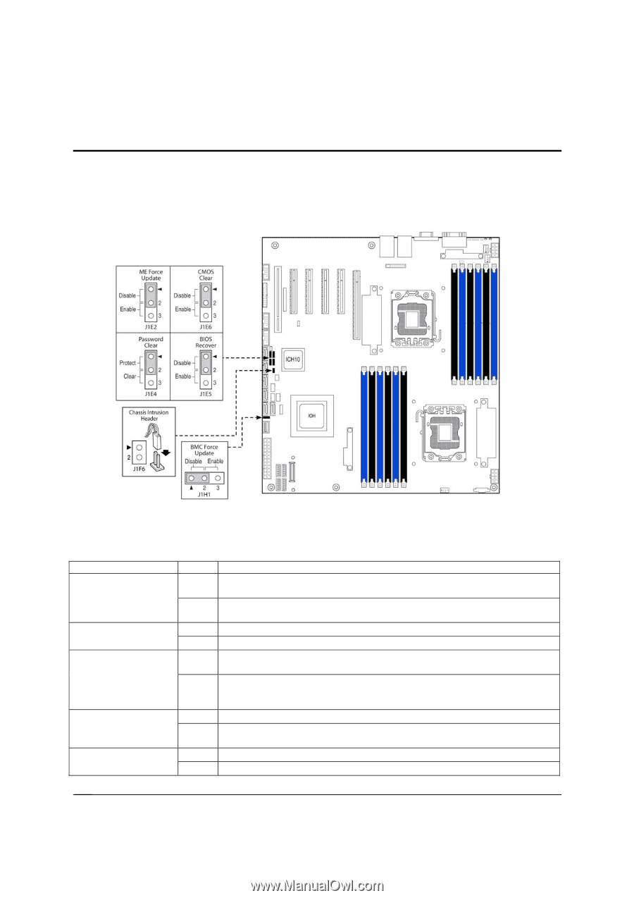
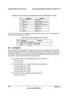
Jumper Blocks Intel® Server Boards S5520HC, S5500HCV, and S5520HCT TPS 7. Jumper Blocks The server boards have several 3-pin jumper blocks that you can use to configure, protect, or recover specific features of the server boards. The following symbol identifies Pin 1 on each jumper block on the silkscreen: ▼ Figure 53. Jumper Blocks (J1E2, J1E4, J1E5, J1E6, J1H1) Table 69. Server Board Jumpers (J1E6, J1E2, J1E4, J1E5, J1H1) Jumper Name Pins 1-2 J1E6: CMOS Clear 2-3 J1E2: ME Update Force 1-2 2-3 1-2 J1E4: Password Clear 2-3 1-2 J1E5: BIOS Recovery 2-3 J1H1: Force BMC 1-2 Update 2-3 System Results These pins should have a jumper in place for normal system operation. (Default) If pins 2-3 are connected when AC power unplugged, the CMOS settings clear in 5 seconds. Pins 2-3 should not be connected for normal system operation. ME Firmware Force Update Mode - Disabled (Default) ME Firmware Force Update Mode - Enabled These pins should have a jumper in place for normal system operation. (Default) To clear administrator and user passwords, power on the system with pins 2-3 connected. The administrator and user passwords clear in 5-10 seconds after power on. Pins 2-3 should not be connected for normal system operation. Pins 1-2 should be connected for normal system operation. (Default) The main system BIOS does not boot with pins 2-3 connected. The system only boots from EFI-bootable recovery media with a recovery BIOS image present. BMC Firmware Force Update Mode - Disabled (Default) BMC Firmware Force Update Mode - Enabled 118 Revision 1.8 Intel order number E39529-013
-
 1
1 -
2
-
3
-
4
-
5
-
6
-
7
-
8
-
9
-
10
-
11
-
12
-
13
-
14
-
15
-
16
-
17
-
18
-
19
-
20
-
21
-
22
-
23
-
24
-
25
-
26
-
27
-
28
-
29
-
30
-
31
-
32
-
33
-
34
-
35
-
36
-
37
-
38
-
39
-
40
-
41
-
42
-
43
-
44
-
45
-
46
-
47
-
48
-
49
-
50
-
51
-
52
-
53
-
54
-
55
-
56
-
57
-
58
-
59
-
60
-
61
-
62
-
63
-
64
-
65
-
66
-
67
-
68
-
69
-
70
-
71
-
72
-
73
-
74
-
75
-
76
-
77
-
78
-
79
-
80
-
81
-
82
-
83
-
84
-
85
-
86
-
87
-
88
-
89
-
90
-
91
-
92
-
93
-
94
-
95
-
96
-
97
-
98
-
99
-
100
-
101
-
102
-
103
-
104
-
105
-
106
-
107
-
108
-
109
-
110
-
111
-
112
-
113
-
114
-
115
-
116
-
117
-
118
-
119
-
120
-
121
-
122
-
123
-
124
-
125
-
126
-
 127
127 -
 128
128 -
 129
129 -
 130
130 -
 131
131 -
 132
132 -
 133
133 -
 134
134 -
 135
135 -
 136
136 -
 137
137 -
138
-
139
-
140
-
141
-
142
-
143
-
144
-
145
-
146
-
147
-
148
-
149
-
150
-
151
-
152
-
153
-
154
-
155
-
156
-
157
-
158
-
159
-
160
-
161
-
162
-
163
-
164
-
165
-
166
-
167
-
168
-
169
-
170
-
171
-
172
-
173
-
174
-
175
-
176
-
177
-
178
-
179
-
180
-
181
-
182
-
183
-
184
-
185
-
186
-
187
-
188
-
189
-
190
 |
 |