Contents
v
5 Technical Reference
Server Board Connectors
...................................................................................................
67
Baseboard Connectors
..............................................................................................
68
Power and Hardware Control Connectors
.........................................................
68
Add-In Board and Peripheral Interface Connectors
...........................................
69
Server Board Resources
....................................................................................................
70
Memory Map
.............................................................................................................
70
DMA Channels
..........................................................................................................
70
I/O Map
.....................................................................................................................
71
Interrupts
...................................................................................................................
72
6 Regulatory and Integration Information
Product Regulatory Compliance
.........................................................................................
73
Product Safety Compliance
.......................................................................................
73
Product EMC Compliance
.........................................................................................
73
Product Certification Markings
...................................................................................
74
Installation Precautions
......................................................................................................
75
Installation Requirements
...................................................................................................
75
Ensure Electromagnetic Compatibility (EMC) Compliance
.........................................
75
Ensure Chassis and Accessory Module Certifications
...............................................
76
Prevent Power Supply Overload
................................................................................
76
Place Battery Marking
................................................................................................
76
Use Only for Intended Applications
............................................................................
76
Figures
1. Back Panel Connectors
..................................................................................................
8
2. Front Panel Connectors
.................................................................................................
9
3. Server Board Components
...........................................................................................
10
4. DIMM Socket Locations
...............................................................................................
21
5. I/O Shield Dimensions
.................................................................................................
22
6.
Location of the Mounting Screw Holes
.........................................................................
23
7.
Installing the Processor in the Processor Socket
.........................................................
24
8.
Attaching the Heatsink to the Processor
......................................................................
25
9.
Attaching the Fan Heatsink Clips to the Processor Socket
...........................................
25
10. Connecting the Processor Fan Cable to the Processor
Fan Connector
.............................................................................................................
26
11. Attaching the Fan Heatsink Over the Processor
..........................................................
27
12. Placing the Plastic Clip Over the Fan Heatsink
............................................................
28
13. Lowering the Plastic Clip Handle
..................................................................................
28
14. Attaching the Fan to the Fan Heatsink
.........................................................................
29
15. Connecting the Processor Fan Cable to the Processor
Fan Connector
.............................................................................................................
29
16. Removing the Fan Heatsink
.........................................................................................
30
17. Removing the Battery
..................................................................................................
33
18. Connecting the IDE Cable
............................................................................................
34
19. BIOS Configuration Jumper Block Location
.................................................................
35
20. Connector Groups
........................................................................................................
67
 1
1 2
2 3
3 4
4 5
5 6
6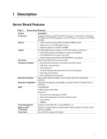 7
7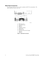 8
8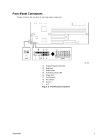 9
9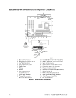 10
10 11
11

