Intel SE7501BR2 Product Guide - Page 42
Attaching the Heat Sink and Retention Clip, retention clip while sliding it to over.
 |
UPC - 735858158053
View all Intel SE7501BR2 manuals
Add to My Manuals
Save this manual to your list of manuals |
Page 42 highlights
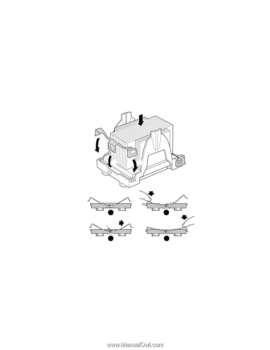
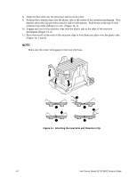
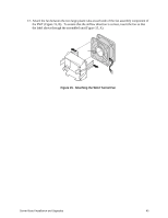
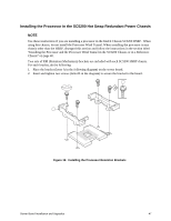
8. Align the heat sink over the processor and set it into place. 9. Position the retention clips over the plastic tabs at the center of the retention mechanism. Note that the slot in the clip provides room for side-to-side motion. Push down on the top of each retention clip while sliding it to over. (Figure 14, 1). 10. Engage each end of the retention clips over the plastic tabs at the sides of the retention mechanism (Figure 14, 2). 11. Press downward on the ends of the retention clips to lock them into place over the plastic tabs (Figure 14, 3 and 4). ✏ NOTE Make sure the center tab engages in the heat sink base. A C B C E 1 3 D 2 4 OM15039A Figure 14. Attaching the Heat Sink and Retention Clip 42 Intel Server Board SE7501BR2 Product Guide
-
 1
1 -
2
-
3
-
4
-
5
-
6
-
7
-
8
-
9
-
10
-
11
-
12
-
13
-
14
-
15
-
16
-
17
-
18
-
19
-
20
-
21
-
22
-
23
-
24
-
25
-
26
-
27
-
28
-
29
-
30
-
31
-
32
-
33
-
34
-
35
-
36
-
 37
37 -
 38
38 -
 39
39 -
 40
40 -
 41
41 -
 42
42 -
 43
43 -
 44
44 -
 45
45 -
 46
46 -
 47
47 -
48
-
49
-
50
-
51
-
52
-
53
-
54
-
55
-
56
-
57
-
58
-
59
-
60
-
61
-
62
-
63
-
64
-
65
-
66
-
67
-
68
-
69
-
70
-
71
-
72
-
73
-
74
-
75
-
76
-
77
-
78
-
79
-
80
-
81
-
82
-
83
-
84
-
85
-
86
-
87
-
88
-
89
-
90
-
91
-
92
-
93
-
94
-
95
-
96
-
97
-
98
-
99
-
100
-
101
-
102
-
103
-
104
-
105
-
106
-
107
-
108
-
109
-
110
-
111
-
112
-
113
-
114
-
115
-
116
-
117
-
118
-
119
-
120
-
121
-
122
-
123
-
124
-
125
-
126
-
127
-
128
-
129
-
130
 |
 |