Intel SR1530HCL Product Specification - Page 13
System Boards, 1.5 Hard Drive and Peripheral Bays, Back Panel Features
 |
View all Intel SR1530HCL manuals
Add to My Manuals
Save this manual to your list of manuals |
Page 13 highlights
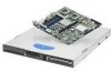
Intel® Server Systems SR1530CL/SR1530HCL/SR1530HCS and SR1530CLR/SR1530HCLR/SR1530HCLSR Introduction Note: The I/O connector locations on the back of the chassis are pre-cut, making an I/O shield unnecessary. The supplied EMI gasket must be installed to maintain electromagnetic interference (EMI) compliance levels. A B C D A AC Power Connector B Mouse Socket C PCI Express* Slot D PCI-X* Slot E Keyboard Socket F I E GH J AF001183 F USB Ports 0 and 1 G Serial Port A H Video Connector I NIC 1 Connector (10/100/1000 Mb) J NIC 1 Connector (10/100/1000 Mb) Figure 5. Back Panel Features 1.4 System Boards The system includes system boards that are used as internal interconnects and provide feature accessibility. The following provides a brief description for each: Riser card - The system supports one PCI riser card that supports up to two add-in cards: ƒ One low-profile PCI Express* x8 and one mid-height PCI-X* 133. ƒ Or one low-profile PCI Express* x4 and one mid-height PCI Express* x4. 1.5 Hard Drive and Peripheral Bays The Intel® Server System SR1530CL/SR1530CLR is designed to support up to two fixed 3.5inch SATA (Serial ATA) hard drives and one slimline optical device. Revision 2.2 5 Intel order number D71005-005
-
 1
1 -
2
-
3
-
4
-
5
-
6
-
7
-
 8
8 -
 9
9 -
 10
10 -
 11
11 -
 12
12 -
 13
13 -
 14
14 -
 15
15 -
 16
16 -
 17
17 -
 18
18 -
19
-
20
-
21
-
22
-
23
-
24
-
25
-
26
-
27
-
28
-
29
-
30
-
31
-
32
-
33
-
34
-
35
-
36
-
37
-
38
-
39
-
40
-
41
-
42
-
43
-
44
-
45
-
46
-
47
-
48
-
49
-
50
-
51
-
52
-
53
-
54
-
55
-
56
 |
 |
