| Section |
Page |
| Intel® Server System SR2500AL User’s Guide |
1 |
| Safety Information |
3 |
| Important Safety Instructions |
3 |
| Wichtige Sicherheitshinweise |
3 |
| Consignes de sécurité |
3 |
| Instrucciones de seguridad importantes |
3 |
| Warnings |
5 |
| Preface |
7 |
| About this Manual |
7 |
| Manual Organization |
7 |
| Product Contents |
8 |
| Intel® Server System SR2500ALLX/SR2500ALLXR Contents |
8 |
| Intel® Server System SR2500ALBRP/SR2500ALBRPR Contents |
9 |
| Table of Contents |
11 |
| List of Figures |
17 |
| List of Tables |
21 |
| 1 Server System References |
23 |
| 2 Server System Features |
25 |
| Figure 1. Intel® Integrated Server System SR2500AL |
25 |
| Chassis Component Identification |
28 |
| Internal Components |
28 |
| A. Rack Handles |
28 |
| B. SAS/SATA Backplane |
28 |
| C. Air Baffles |
28 |
| D. Power Distribution Module |
28 |
| E. Power Supply Module Housing (supports up to two power supply modules) |
28 |
| F. Riser Card Assembly |
28 |
| G. Integrated Chassis Intrusion Switch |
28 |
| H. System Memory (below duct in illustration) |
28 |
| I. Processor Air Duct |
28 |
| J. System Fan Assembly (redundant option shown) |
28 |
| K. Bridge Board |
28 |
| L. Control Panel (standard control panel shown) |
28 |
| M. Flex Bay - 6th HDD or Tape Drive (optional) |
28 |
| N. Hard Drive Bays |
28 |
| O. Slimline Optical Drive Bay |
28 |
| Figure 2. ChassisComponents |
28 |
| A. BIOS Bank Select Jumper |
30 |
| B. Intel® 6321ESB IO Controller Hub |
30 |
| C. I/O Expansion Module Connector |
30 |
| D. POST Code Diagnostic LEDs |
30 |
| E. Intel® Adaptive Slot - Full Height |
30 |
| F. PCI Express* Riser Slot - Low Profile |
30 |
| G. System Identification LED - Blue |
30 |
| H. Back Panel I/O Ports |
30 |
| I. Status LED - Green/Amber |
30 |
| J. Serial B Configuration Jumper |
30 |
| K. System Fan 4 Header |
30 |
| L. System Fan 3Header |
30 |
| M. DIMM Sockets |
30 |
| N. Intel® 5000P MCH or Intel® 5000X MCH |
30 |
| O. Processor 1 Socket |
30 |
| P. Processor 2 Socket |
30 |
| Q. Processor Fan 1 Header |
30 |
| R. Voltage Regulator Heat Sink |
30 |
| S. Processor Fan 2 Header |
30 |
| T. Bridge Board Connector |
30 |
| U. ATA-100 Optical Drive Connector (Power + IO) |
30 |
| V. System Fan 2 Header |
30 |
| W. CPU Power Connector |
30 |
| X. Main Power Connector |
30 |
| Y. Battery |
30 |
| Z. Power Supply Management Connector |
30 |
| AA. Dual Port USB 2.0 Header |
30 |
| BB. System Fan 1 Header |
30 |
| CC. 24-pin SSI Control Panel Connector |
30 |
| DD. SATA Port 0 |
30 |
| EE. SATA Port 1 |
30 |
| FF. SATA Port 2 |
30 |
| GG. SATA Port 3 |
30 |
| HH. SATA Port 4 |
30 |
| II. SATA Port 5 |
30 |
| JJ. SATA SW RAID 5 Activation Key Connector |
30 |
| KK. Intel® Remote Management Module (RMM) Connector |
30 |
| LL. System Recovery Jumpers |
30 |
| MM. Chassis Intrusion Switch Header |
30 |
| NN. 3-pin IPMB Header |
30 |
| OO. Intel® Local Control Panel Header |
30 |
| PP. Serial A Header |
30 |
| QQ. Intel® RMM NIC Connector |
30 |
| Figure 3. Server Board Connector and Component Locations |
30 |
| Configuration Jumpers |
31 |
| Figure 4. BIOS Select Jumper |
31 |
| Figure 5. Recovery Jumpers |
32 |
| Intel® Light Guided Diagnostics |
33 |
| Figure 6. Light Guided Diagnostic LEDs |
33 |
| Back Panel Connectors |
34 |
| A. Mouse |
34 |
| B. Keyboard |
34 |
| C. Serial Port B (RJ45) |
34 |
| D. NIC 1 (10/100/1000 Mb) |
34 |
| E. NIC 2 (10/100/1000 Mb) |
34 |
| F. Video |
34 |
| G. USB Port 6 |
34 |
| H. USB Port 5 |
34 |
| Figure 7. Back Panel Connectors |
34 |
| RAID Support |
35 |
| SAS/SATA Mid-Planes |
36 |
| A. Mid-plane Power |
36 |
| B. Fan 6 Power |
36 |
| C. Fan 5 Power |
36 |
| D. SATA 0-7 Connectors |
36 |
| E. Bridge Board Connector |
36 |
| F. Fan 4 Power |
36 |
| G. Fan 3 Power |
36 |
| H. Fan 1 Power |
36 |
| I. Fan 2 Power |
36 |
| J. Backplane Connectors |
36 |
| Figure 8. Passive Mid-Plane Components |
36 |
| Note: SATA connectors 6 and 7 are not used in the Intel® Server System SR2500ALLX and/or the Intel® Server System SR2500ALBRP. |
36 |
| A. RAID Battery Connector |
37 |
| B. Mid-plane Power Connector |
37 |
| C. Fan 6 Power |
37 |
| D. Fan 5 Power |
37 |
| E. Bridge Board Connector |
37 |
| F. Fan 4 Power |
37 |
| G. Fan 3 Power |
37 |
| H. Fan 2 Power |
37 |
| I. Fan 1 Power |
37 |
| J. Backplane Connectors |
37 |
| Figure 9. Active SAS/SATA Mid-Plane Components |
37 |
| Hot-Swap SAS/SATA Backplane |
38 |
| A. Optical Drive Connector |
38 |
| B. USB Floppy Connector |
38 |
| C. Control Panel Connector |
38 |
| D. SAS/SATA Connectors |
38 |
| Figure 10. Hot-Swap SAS/SATA Backplane Components (Front View) |
38 |
| A. Flex Bay Power |
39 |
| B. Flex Bay Data |
39 |
| C. IDE Connector |
39 |
| D. Backplane Power |
39 |
| E. Data Connectors (one for the flex bay and one for the mid-plane) |
39 |
| Figure 11. Hot-Swap SAS/SATA Backplane Components (Rear View) |
39 |
| Front of Server System |
40 |
| Standard Control Panel |
40 |
| A. |
40 |
| B. |
40 |
| C. |
40 |
| D. |
40 |
| E. |
40 |
| F. |
40 |
| G. |
40 |
| H. |
40 |
| I. |
41 |
| J. |
41 |
| K. |
41 |
| L. |
41 |
| Figure 12. Standard Control Panel |
41 |
| Intel® Local Control Panel |
41 |
| A. |
41 |
| B. |
41 |
| C. |
41 |
| D. |
41 |
| E. |
41 |
| F. |
41 |
| G. |
41 |
| H. |
41 |
| I. |
42 |
| J. |
42 |
| K. |
42 |
| L. |
42 |
| M. |
42 |
| N. |
42 |
| O. |
42 |
| Figure 13. Intel® Local Control Panel |
42 |
| Bezels |
42 |
| Rear of Server System |
43 |
| A. Low Profile Add-in Card Slots |
43 |
| B. Full Height PCI Add-in Card Slots |
43 |
| C. Upper Power Supply Module |
43 |
| D. Upper Power Receptacle |
43 |
| E. Lower Power Receptacle |
43 |
| F. Lower Power Supply Module |
43 |
| G. Server Management NIC (Optional) |
43 |
| H. I/O Module (Optional) |
43 |
| I. USB 6 |
43 |
| J. USB 5 |
43 |
| K. Video |
43 |
| L. DB-9 Serial A Connector Knockout |
43 |
| M. NIC 2 |
43 |
| N. NIC 1 |
43 |
| O. RJ45 Serial B Connector |
43 |
| P. PS2* Keyboard and Mouse Connectors |
43 |
| Figure 14. Server System Back |
43 |
| Peripheral Devices |
44 |
| A. Slimline Optical Drive Bay |
44 |
| B. Tape Drive Filler Panel |
44 |
| C. 6th HDD or Tape Drive Bay (Optional) |
44 |
| D. Hard Disk Drive Bays |
44 |
| E. HDD to Floppy Drive Conversion (Optional) |
44 |
| Figure 15. Optional Peripherals |
44 |
| Hard Disk Drives |
44 |
| Note: SAS drives are supported on the Intel® Server System SR2500ALLX/SR2500ALLXR only. |
44 |
| Note: Drives can consume up to 17 watts of power each. Drives must be specified to run at a maximum ambient temperature of 45C. |
44 |
| Note: The Intel® Server System SR2500ALLX and/or the Intel® Server System SR2500ALBRP does not support all SAS or Serial ATA (SATA) hard drives. See “Server System References” for an Internet link to a list of supported hardware. |
44 |
| Slimline Optical Drive Carrier |
45 |
| Note: The Intel® Server System SR2500ALLX and/or the Intel® Server System SR2500ALBRP does not support all slimline optical driv... |
45 |
| Advanced Management Options |
45 |
| Intel® Remote Management Module |
45 |
| Rack-Mounted Systems |
45 |
| 3 Hardware Installations and Upgrades |
47 |
| Before You Begin |
47 |
| Tools and Supplies Needed |
47 |
| System References |
47 |
| Removing and Installing from a Rack |
47 |
| Note: Follow all safety guidelines while removing a system from a rack to avoid injury. |
47 |
| Fixed Bracket Rack Mount Removal |
47 |
| 1. Disconnect all cables from the back of the system. |
47 |
| Note: Remember to use the system LED to properly identify the system you are servicing. |
47 |
| 2. Remove screws from the brackets and remove the system from the rack. |
47 |
| Fixed Bracket Rack Mount Installation |
48 |
| 1. Fully extend a rail assembly; the finger tab for the extension lock is revealed. |
48 |
| 2. Press the finger tab and slide the inside rail from the middle rail until it completely separates. |
48 |
| Note: The middle rail and outer rail cannot be separated. |
48 |
| 3. Position an inside rail along one side of the chassis with the finger tab facing outward and located closer to the rear of the chassis. |
48 |
| 4. Align the holes in the rail with the tabs on the chassis and place the rail against the chassis. |
48 |
| 5. Slide the rail as far as it will go toward the front of the chassis to engage the tabs. |
48 |
| 6. Fasten the rail to the chassis using one screw at the front of the chassis. |
48 |
| 7. In the same manner, attach the other inside rail to the other side of the chassis |
48 |
| 8. Using two screws, attach one nut bar to the inside of the rack post. Do not completely tighten the screws; leave them loose enough to allow insertion of the brackets in the next step. |
48 |
| 9. Insert the slotted foot of a rail bracket between each nut bar and post. |
48 |
| 10. Align the face of the bracket foot with the inside edge of the rack post and firmly tighten the screws. |
48 |
| 11. Repeat steps 8 to 10 above to install the other 3 brackets (2 front & 2 back). Ensure all brackets are at the same height on the rack. |
48 |
| 12. Position a rail assembly (middle and outer rails) with its black plastic end caps toward the rear of the rack and its outer rail closest to the brackets. |
48 |
| 13. Align the front screw hole in the outer rail with the threaded hole nearest the front of the front bracket and fit the rail assembly into the front and rear brackets. |
48 |
| 14. Slide the middle rail toward the front until the access hole in the middle rail is aligned with the front screw hole in the outer rail. |
48 |
| 15. Insert screw through the access hole and loosely attach the outer rail to the front bracket. |
48 |
| 16. In a similar manner to steps 13 through 15, install a screw through a slot in the outer rail and into the rear-most threaded hole in the front bracket. Firmly tighten this screw. |
48 |
| 17. Firmly tighten the front screw installed loosely in step 15. |
48 |
| 18. In the same manner, attach the other rail assembly to the other side. |
48 |
| 19. Slide the middle rail toward the front until the rear bracket area is accessible. |
48 |
| 20. Attach the rear end of the outer rail to the rear bracket with at least one screw. If possible, attach at two places. |
48 |
| 21. In the same manner, attach the other rail assembly to the other side. |
48 |
| 22. Fully extend the left and right rails until the extension locks have engaged and the rails will not push back in. The rail system is now ready to receive the chassis. |
49 |
| Caution: Lifting and placing the chassis in the rails is a two-person job. If needed, use an appropriate lifting device. |
49 |
| 23. With the chassis front facing you, lift the chassis and carefully insert the rails attached to the chassis in the extended rails. |
49 |
| 24. Slide the chassis toward the rear of the cabinet until the rails lock together. |
49 |
| 25. Depress and hold down the finger tabs on both extension locks while sliding the chassis toward the rear. |
49 |
| 26. Slide the chassis all the way into the rack until the chassis handles are against the front posts. |
49 |
| Basic Rail Rack Mount Removal |
49 |
| 1. Disconnect all cables from the back of the system. |
49 |
| Note: Remember to use the system LED to properly identify the system you are servicing. |
49 |
| 2. Pull system from rack until brackets are fully extended. |
49 |
| 3. Push in both clips on the brackets and slide the system forward until the inner rail separates from the outer rail. |
49 |
| 4. Remove and service the system. |
49 |
| Basic Rail Rack Mount Installation |
49 |
| 1. Extend the inner rail until it locks. |
49 |
| 2. Depress the spring safety lock to release the inner rail. |
49 |
| 3. Remove the inner rail from the rail assembly. |
49 |
| 4. Attach the outer rail slides to the rack posts using two #10-32 x 1/2 screws at the front posts, and two #10-32 x 1/2 screws at the rear posts. |
49 |
| Note: The rail flanges mount to the inside of each post. |
49 |
| 5. Insert the inner rails over the server chassis sidewall studs. |
49 |
| 6. Slide the inner rails toward the front of the server chassis. |
49 |
| 7. Secure the inner rails with one #6-32 x 1/4 screw for each rail. |
49 |
| 8. Align the inner rails (attached to the server chassis) with the outer rail assemblies (attached to the rack). |
49 |
| 9. Engage the matching rails and slide the server chassis into the rack until the two safety stops lock into position. |
49 |
| 10. Depress the two safety locks (one on each side). |
49 |
| 11. Slide the server chassis all the way into the rack. |
50 |
| 12. Use the rack screws (#10-32 x 3/4) to secure the chassis and rack handles into the rack. |
50 |
| Tool-less Rail Rack Mount Servicing |
50 |
| 1. To service the system, pull the system out from the rack. |
50 |
| 2. Disconnect the power cable(s) and proceed with servicing the system. |
50 |
| 3. When the servicing is completed, re-connect the power cable(s). |
50 |
| 4. Pull up on the green tabs on each rail and slide the system back into the rack. |
50 |
| Note: Beware of cables when re-installing the system into the rack so that the cables do not get pulled or interfered with. |
50 |
| Removing and Installing the Front Bezel |
50 |
| Figure 16. Front Bezel Supporting the Standard Control Panel |
50 |
| Figure 17. Front Bezel Supporting the Intel® Local Control Panel |
50 |
| Removing the Front Bezel |
51 |
| 1. Unlock the bezel. |
51 |
| 2. Disconnect any cables attached to the control panel. |
51 |
| 3. Pull the bezel from the server system. |
51 |
| Figure 18. Removing the Front Bezel |
51 |
| Installing the Front Bezel |
52 |
| 1. At each end of the bezel, line up the center notch on the bezel with the center guide on the rack handles. |
52 |
| 2. Push the bezel onto the front of the server system until it clicks into place. |
52 |
| 3. Connect any necessary cables to the front control panel area at the right side of the server system. |
52 |
| Figure 19. Installing the Front Bezel |
52 |
| Removing and Installing the System Cover |
52 |
| Removing the System Cover |
52 |
| Note: A nonskid surface or a stop behind the server system may be needed to prevent the server system from sliding on your work surface. |
52 |
| 1. Observe the safety and ESD precautions at the beginning of this book. See “Safety Information”. |
53 |
| 2. Turn off all peripheral devices connected to the server. Turn off the server. |
53 |
| 3. Disconnect the AC power cord(s). |
53 |
| 4. Remove the safety screw if it is installed. See letter \ |
53 |
| 5. While holding in the blue button at the top of the server system in (see letter \ |
53 |
| 6. Insert your finger in the notch (see letter “D”) and lift the cover upward to remove it. |
53 |
| Figure 20. Removing the Server System Cover |
53 |
| Installing the Server System Cover |
53 |
| 1. Place the cover over the server system so that the side edges of the cover sit just inside the server system sidewalls. |
53 |
| 2. Slide the cover forward until it clicks into place (see letter “A”). |
53 |
| 3. (Optional) Insert the safety screw at the center of the top cover (see letter “B”) if required. |
53 |
| 4. Reconnect all peripheral devices and the AC power cord(s). |
53 |
| Figure 21. Installing the Server System Cover |
54 |
| Removing and Installing the Processor Air Duct |
54 |
| Removing the Processor Air Duct |
54 |
| 1. Observe the safety and ESD precautions at the beginning of this book. See \ |
54 |
| 2. Power down the server and unplug all peripheral devices and the AC power cable. |
54 |
| 3. Remove the server system cover. For instructions, see “Removing the System Cover”. |
54 |
| 4. Lift the processor air duct from its location over the two processor sockets. |
54 |
| Figure 22. Removing the Processor Air Duct |
55 |
| Installing the Processor Air Duct |
56 |
| 1. Observe the safety and ESD precautions at the beginning of this book. See \ |
56 |
| 2. Power down the server and unplug all peripheral devices and the AC power cable(s). |
56 |
| 3. Remove the server system cover. For instructions, see “Removing the System Cover”. |
56 |
| 4. Turn processor air duct over to reveal underside (see letter “A”). |
56 |
| 5. If two processors are installed: remove air dam (see letter “B”) by sliding slotted holes off duct pins. |
56 |
| Do not remove memory air deflector. |
56 |
| Figure 23. Removing the Processor 2 Air Dam (Optional - only if two processors are installed) |
56 |
| 6. Place the processor air duct over the processor socket(s). See the figure below. The front edge of the air duct should contact the fan module. Use caution not to pinch or disengage cables that may be near or under the air duct. |
56 |
| 7. Install the server system cover. For instructions, see “Installing the Server System Cover”. |
56 |
| 8. Plug all peripheral devices and the AC power cable(s) into the server. |
56 |
| Figure 24. Installing the Processor Air Duct |
57 |
| Installing and Removing Memory |
57 |
| Installing DIMMs |
57 |
| 1. Observe the safety and ESD precautions in “Safety Information”. |
57 |
| 2. Turn off all peripheral devices connected to the server. Turn off the server. |
57 |
| 3. Disconnect the AC power cord(s) from the server. |
57 |
| 4. Remove the server's cover. See the documentation that came with your server chassis for instructions on removing the server's cover. |
57 |
| 5. Locate the DIMM sockets (see Figure 25). |
57 |
| Figure 25. Installing the Memory |
58 |
| 6. Make sure the clips at either end of the DIMM socket(s) are pushed outward to the open position (see letter “A” in the figure above). |
58 |
| 7. Holding the DIMM by the edges, remove it from its anti-static package. |
58 |
| 8. Position the DIMM above the socket. Align the notch on the bottom edge of the DIMM with the key in the DIMM socket. The arrow in the inset in Figure 7 is pointing to the key in the socket (see letter “B” in the figure above). |
58 |
| 9. Insert the bottom edge of the DIMM into the socket. |
58 |
| 10. When the DIMM is inserted, push down on the top edge of the DIMM until the retaining clips snap into place (see letter “C” in the figure above). Make sure the clips are firmly in place (see letter “D” in the figure above). |
58 |
| 11. Replace the server's cover and reconnect the AC power cord(s). See the documentation that came with your server chassis for instructions on installing the server's cover. |
59 |
| Removing DIMMs |
59 |
| 1. Observe the safety and ESD precautions in “Safety Information”. |
59 |
| 2. Turn off all peripheral devices connected to the server. Turn off the server. |
59 |
| 3. Remove the AC power cord(s) from the server. |
59 |
| 4. Remove the server's cover. See the documentation that came with your server chassis for instructions on removing the server's cover. |
59 |
| 5. Gently spread the retaining clips at each end of the socket. The DIMM lifts from the socket. |
59 |
| 6. Holding the DIMM by the edges, lift it from the socket, and store it in an anti-static package. |
59 |
| 7. Reinstall and reconnect any parts you removed or disconnected to reach the DIMM sockets. |
59 |
| 8. Replace the server's cover and reconnect the AC power cord(s). See the documentation that came with your server chassis for instructions on installing the server's cover. |
59 |
| Caution: Processor must be appropriate: You may damage the server board if you install a processor that is inappropriate for your server. See “Server System References” for a link to the list of compatible processor(s). |
59 |
| Caution: ESD and handling processors: Reduce the risk of electrostatic discharge (ESD) damage to the processor by doing the foll... |
59 |
| Caution: Protective socket cover needs to be removed for proper cooling of the processor; failure to remove the cover could result in damage to the system. |
59 |
| Installing the Processor |
59 |
| 1. Observe the safety and ESD precautions in “Safety Information”. |
59 |
| 2. Turn off all peripheral devices connected to the server. Turn off the server. |
59 |
| 3. Disconnect the AC power cord(s) from the server. |
60 |
| 4. Remove the server's cover. See the documentation that came with your server chassis for instructions on removing the server's cover. |
60 |
| 5. Locate the processor socket and raise the socket handle completely (see Figure 26). |
60 |
| Figure 26. Lifting the Processor Socket Handle |
60 |
| 6. Raise the CPU load plate (see Figure 27). |
60 |
| Figure 27. Installing the Processor |
60 |
| Note: Do not touch the socket pins; they are very sensitive and easily damaged. |
60 |
| 7. Line up the alignment marks on the processor and the socket, and insert the processor into the socket. |
60 |
| Note: Make sure the alignment triangle mark and the alignment triangle cutout align correctly. |
60 |
| 8. Remove the protective socket cover (see Figure 28). |
60 |
| Note: Retain the protective socket cover for use when removing a processor that will not be replaced. |
60 |
| Figure 28. Removing the Socket Cover |
61 |
| 9. Lower the CPU load plate and lower the socket lever completely. |
61 |
| Installing the Heat Sink(s) |
61 |
| 1. Set the heat sink over the processor, lining up the four captive screws with the four posts surrounding the processor. |
61 |
| 2. Loosely screw in the captive screws on the heat sink corners in a diagonal manner. Do no fully tighten one screw before tightening another. |
61 |
| 3. Gradually and equally tighten each captive screw until each is firmly tightened. |
61 |
| Figure 29. Installing the Heat Sink (2U Passive Heat Sink Shown) |
61 |
| 4. Reinstall and reconnect any parts you removed or disconnected to reach the processor sockets. |
62 |
| 5. Replace the server's cover and reconnect the AC power cord(s). See the documentation that came with your server chassis for instructions on installing the server's cover. |
62 |
| Removing a Processor |
62 |
| 1. Observe the safety and ESD precautions in “Safety Information”. |
62 |
| 2. Turn off all peripheral devices connected to the server. Turn off the server. |
62 |
| 3. Remove the AC power cord(s) from the server. |
62 |
| 4. Remove the server's cover. See the documentation that came with your server chassis for instructions on removing the server's cover. |
62 |
| 5. Unplug the processor fan cable from the server board. |
62 |
| 6. Loosen the four captive screws on the corners of the heat sink. |
62 |
| 7. Twist the heat sink slightly to break the seal between the heat sink and the processor. |
62 |
| 8. Lift the heat sink from the processor. If it does not pull up easily, twist the heat sink again. Do not force the heat sink from the processor. Doing so could damage the processor. |
62 |
| 9. Lift the processor lever. |
62 |
| 10. Raise the CPU load plate. |
62 |
| 11. Remove the processor. |
62 |
| 12. If installing a replacement processor, see “Installing the Processor”. Otherwise, install the protective socket cover over the empty processor socket and reinstall the chassis cover. |
62 |
| Removing and Installing the Small Air Baffle |
62 |
| Removing the Small Air Baffle |
63 |
| 1. Observe the safety and ESD precautions at the beginning of this book. See “Safety Information”. |
63 |
| 2. Power down the server and unplug all peripheral devices and the AC power cable(s). |
63 |
| 3. Remove the server system cover. For instructions, see “Removing the System Cover”. |
63 |
| 4. Pull up and out on the air baffle to remove it. See the figure below. |
63 |
| Figure 30. Removing the Small Air Baffle |
63 |
| Installing the Small Air Baffle |
63 |
| 1. Lower the baffle into the server system. |
63 |
| 2. Snap the baffle into place as shown in the figure below. |
63 |
| Figure 31. Installing the Small Air Baffle |
64 |
| 3. Install the server system cover. For instructions, see “Installing the Server System Cover”. |
64 |
| 4. Plug all peripheral devices and the AC power cable(s) into the server. |
64 |
| Removing and Installing the Large Air Baffle |
64 |
| Removing the Large Air Baffle |
64 |
| 1. Observe the safety and ESD precautions at the beginning of this book. See “Safety Information”. |
64 |
| 2. Power down the server and unplug all peripheral devices and the AC power cable(s). |
64 |
| 3. Remove the server system cover. For instructions, see “Removing the System Cover”. |
64 |
| 4. Note how the cables are routed over and under the air baffle (if any). You will need to re-route these cables. |
64 |
| 5. Pull up on the air baffle to remove it. See the figure below. You may need to remove or hold cables out of the way. |
65 |
| Figure 32. Removing the Large Air Baffle |
65 |
| Installing the Large Air Baffle |
65 |
| 1. Lower the baffle into the server system and snap into the server board standoff as shown in the figure below. |
65 |
| 2. While setting the baffle into place, route the cables beneath it appropriately. See Appendix , “Cable Routing” or the Quick Reference Label that came with your system for help in determining where the cables should be routed. |
65 |
| Figure 33. Installing the Large Air Baffle |
66 |
| 3. Install the server system cover. For instructions, see “Installing the Server System Cover”. |
66 |
| 4. Plug all peripheral devices and the AC power cable(s) into the server. |
66 |
| Installing and Removing a Hot-swap Hard Drive |
66 |
| To avoid possible damage to your server system, do not use older style drive carriers. |
66 |
| Note: The server system does not support all hard drives. See “Server System References“ for an Internet link to a list of supported hardware. |
66 |
| Installing a SAS or SATA Hot-swap Hard Disk Drive |
66 |
| 1. Remove the front bezel if it is installed. For instructions, see “Removing the Front Bezel”. |
66 |
| 2. Open the latch at the front of the hard drive carrier. See letter \ |
66 |
| 3. Pull out on the black lever and slide the carrier from the server system. See letter \ |
67 |
| Figure 34. Removing Hot-swap Disk Carrier from the Server System |
67 |
| 4. Remove the four screws that attach the plastic retention device or the previously installed hard drive to the drive carrier. Two screws are at each side of the retention device or the hard drive. Store the plastic retention device for future use. |
67 |
| Figure 35. Removing Retention Device from Drive Carrier |
67 |
| 5. Remove the hard drive from its wrapper and place it on an antistatic surface. |
67 |
| 6. Set any jumpers and/or switches on the drive according to the drive manufacturer's instructions. |
67 |
| 7. With the drive circuit-side down, position the connector end of the drive so that it is facing the rear of the drive carrier. |
67 |
| 8. Align the holes in the drive to the holes in the drive carrier and attach it to the carrier with the screws that were attached to the plastic retention device. |
67 |
| Figure 36. Installing Hard Drive into Carrier |
68 |
| 9. With the black lever in the fully open position, slide the drive assembly into the server system. The green latch at the fron... |
68 |
| 10. When the black drive carrier lever begins to close by itself, push on it to lock the drive assembly into place. |
68 |
| Figure 37. Install Drive Assembly into the Server System |
68 |
| 11. Install the server system cover. For instructions, see “Installing the Server System Cover”. |
68 |
| 12. (Optional) Install the front bezel. For instructions, see “Installing the Front Bezel”. |
68 |
| 13. Plug all peripheral devices and the AC power cable(s) into the server. |
68 |
| Removing a SAS or SATA Hot-swap Hard Disk Drive |
69 |
| 1. Remove the front bezel if it is installed. For instructions, see “Removing the Front Bezel”. |
69 |
| 2. Press in on the green latch at the front of the hard drive carrier. |
69 |
| 3. Pull out on the black lever to slide the carrier from the server system. |
69 |
| 4. Remove the four screws that attach the hard drive to the drive carrier. Lift the drive from the carrier. Store the drive in an anti-static bag. |
69 |
| 5. If you are not installing a new drive, place the plastic retention device into the drive carrier, using the four screws you removed from the hard drive. |
69 |
| 6. Insert the screws that held the drive in the carrier into the screw locations on the carrier for future use. |
69 |
| 7. With the black lever in the fully open position, slide the drive carrier into the server system. The green latch must be to the right. Do not push on the black lever until the lever begins to close by itself. |
69 |
| Note: For proper airflow, the hard drive carrier must be replaced in the server system, even if no hard drive is installed in it. |
69 |
| 8. When the black lever begins to close by itself, push on it to lock the drive carrier into place. |
69 |
| 9. Install the server system cover. For instructions, see “Installing the Server System Cover”. |
69 |
| 10. (Optional) Install the front bezel. For instructions, see “Installing the Front Bezel”. |
69 |
| 11. Plug all peripheral devices and the AC power cable(s) into the server. |
69 |
| Installing or Removing a Slimline Optical Drive or Internal USB Floppy |
69 |
| To maintain proper system cooling, a filler blank must be installed if you do not install a device at this location. |
69 |
| Installing a Slimline Optical Drive or Internal USB Floppy |
70 |
| 1. Observe the safety and ESD precautions at the beginning of this book. See “Safety Information”. |
70 |
| 2. Power down the server and unplug all peripheral devices and the AC power cable(s). |
70 |
| 3. Remove the front bezel if it is installed. For instructions, see “Removing the Front Bezel”. |
70 |
| 4. Remove the server system cover. For instructions, see “Removing the System Cover”. |
70 |
| 5. Insert the interposer board into the optical drive. |
70 |
| 6. Obtain the optical drive and the drive tray. |
70 |
| 7. Align the two holes on the left edge of the optical drive and interposer board with the two metal tabs in the tray as shown in Figure 38 (see letter “A”). |
70 |
| 8. Lower the opposite side of the optical drive into the tray until it clicks into place (see letter “B”). |
70 |
| Figure 38. Installing an Optical Drive into the Drive Tray |
70 |
| 9. Screw the interposer board into the carrier. |
70 |
| 10. Insert the optical drive tray assembly into the server system as shown in Figure 39 (see letter “A”). |
70 |
| 11. Make sure that the back end of the interposer board plugs into the matching socket on the backplane (see letter “B”). |
70 |
| 12. Verify that the blue release lever on the tray locks into place. |
70 |
| 13. (Optional) For installing the optional USB floppy drive, note the location of the backplane USB connector in Figure 39 (see letter “C”) and refer to the documentation that came with the device. |
70 |
| Figure 39. Installing an Optical Drive Assembly into the Server System |
71 |
| 14. Install the server system cover. For instructions, see “Installing the Server System Cover”. |
71 |
| 15. (Optional) Install the front bezel. For instructions, see “Installing the Front Bezel”. |
71 |
| 16. Plug all peripheral devices and the AC power cable(s) into the server. |
71 |
| Removing a Slimline Optical Drive or Internal USB Floppy |
71 |
| 1. Observe the safety and ESD precautions at the beginning of this book. See “Safety Information”. |
71 |
| 2. Power down the server and unplug all peripheral devices and the AC power cable(s). |
71 |
| 3. Remove the front bezel if it is installed. For instructions, see “Removing the Front Bezel”. |
71 |
| 4. Remove the server system cover. For instructions, see “Removing the System Cover”. |
71 |
| 5. If removing an internal USB floppy drive, unplug it from the backplane. |
71 |
| 6. Press the blue release lever (see letter “A”) to unlock the optical drive tray and remove the slimline optical drive tray assembly from the server system as shown in Figure 40. |
71 |
| Figure 40. Removing the Slimline Optical Drive Assembly from the Server System |
72 |
| 7. Press downward on the side of the tray (see letter “A”) and disengage the drive from the two metal tabs on the opposite side of the tray (see letter “B”). |
72 |
| 8. Lift up on the optical drive (see letter “C”) to remove it from the tray. |
72 |
| Figure 41. Removing the Slimline Optical Drive from the Tray |
72 |
| 9. If no device will be installed in this location, install a filler blank as shown in Figure 42. |
73 |
| Figure 42. Installing Filler Blank into the Server System |
73 |
| 10. Install the server system cover. For instructions, see “Installing the Server System Cover”. |
73 |
| 11. (Optional) Install the front bezel. For instructions, see “Installing the Front Bezel”. |
73 |
| 12. Plug all peripheral devices and the AC power cable(s) into the server. |
73 |
| Installing a Tape Drive |
73 |
| 1. Observe the safety and ESD precautions at the beginning of this book. See “Safety Information”. |
73 |
| 2. Power down the server and unplug all peripheral devices and the AC power cable(s). |
73 |
| 3. Remove the front bezel if it is installed. For instructions, see “Removing the Front Bezel”. |
73 |
| 4. Remove the server system cover. For instructions, see “Removing the System Cover”. |
74 |
| 5. Remove the tape drive filler panel from the server system by using a long screwdriver to push it out from the inside of the server system. See the figure below to locate the tape drive filler panel. |
74 |
| Figure 43. Removing Tape Drive Filler Panel from the Server System |
74 |
| 6. Remove the hard drive blank that is installed in the sixth drive bay. See the figure below to locate the sixth drive filler panel. |
74 |
| Figure 44. Removing Sixth Drive Filler Panel from the Server System |
74 |
| 7. Attach the tape drive to the tape drive carrier kit using the four screws that were included with the tape drive kit. See the figure below. |
75 |
| Figure 45. Inserting a Tape Drive into the Carrier |
75 |
| 8. Slide the tape drive carrier with the installed tape drive into the combined tape drive bay/sixth drive bay until the carrier clicks into place. |
75 |
| Figure 46. Installing Tape Drive Assembly into the Server System |
75 |
| 9. See the documentation that came with your tape drive for data cable connection information. |
76 |
| 10. Connect the 4-pin tape power cable to the tape drive. |
76 |
| 11. Install the server system cover. For instructions, see “Installing the Server System Cover”. |
76 |
| 12. (Optional) Install the front bezel. For instructions, see “Installing the Front Bezel”. |
76 |
| 13. Plug all peripheral devices and the AC power cable(s) into the server. |
76 |
| Installing a Sixth Hard Drive |
76 |
| 1. Observe the safety and ESD precautions at the beginning of this book. See “Safety Information”. |
76 |
| 2. Power down the server and unplug all peripheral devices and the AC power cable(s). |
76 |
| 3. Remove the front bezel if it is installed. For instructions, see “Removing the Front Bezel”. |
76 |
| 4. Remove the server system cover. For instructions, see “Removing the System Cover”. |
76 |
| 5. Slide the sixth HDD bracket into the backplane as shown in the figure below. |
76 |
| Figure 47. Installing Sixth HDD Bracket |
76 |
| 6. The sixth hard drive kit comes with a power cable and two SATA cables. Cabling for the sixth hard drive varies depending on w... |
77 |
| 7. If you have an active mid-plane in your system, install the power cable to the backplane and the sixth HDD board (see letter “A”). Install the short SATA cable to the backplane and the sixth HDD board (see letter “B”). Proceed to step 9. |
77 |
| Figure 48. Installing Power and SATA Cables (Active Mid-Plane Installed) |
77 |
| Note: You will not use the long SATA cable from the 6th HDD kit in a system with an active mid- plane. |
77 |
| 8. If you have a passive mid-plane installed in your system, install the power cable to the backplane and the sixth HDD board (s... |
78 |
| Figure 49. Installing Power and SATA Cables (Passive Mid-Plane Installed) |
78 |
| Note: You will not use the short SATA cable from the 6th HDD kit in a system with a passive mid- plane. |
78 |
| 9. Install a hard drive into the sixth hard drive bay. For instructions, see “Installing a SAS or SATA Hot-swap Hard Disk Drive”. |
78 |
| 10. Install the server system cover. For instructions, see “Installing the Server System Cover”. |
78 |
| 11. (Optional) Install the front bezel. For instructions, see “Installing the Front Bezel”. |
78 |
| 12. Plug all peripheral devices and the AC power cable(s) into the server. |
78 |
| Filling Empty Server System Bays |
79 |
| Figure 50. Installing the Filler Panels |
79 |
| Installing and Removing the PCI Riser Assembly |
79 |
| Removing the PCI Riser Assembly |
79 |
| 1. Observe the safety and ESD precautions at the beginning of this book. See “Safety Information”. |
79 |
| 2. Power down the server and unplug all peripheral devices and the AC power cable(s). |
79 |
| 3. Remove the server system cover. For instructions, see “Removing the System Cover”. |
80 |
| 4. Remove the processor air duct by lifting straight up. |
80 |
| 5. Disconnect any cables attached to any add-in cards. |
80 |
| 6. Grasp both riser latches with thumb and forefinger (see letter “A”), and pull up to release riser assembly. |
80 |
| 7. Lift riser assembly straight up (see letter “B”). |
80 |
| Figure 51. Removing PCI Riser Assembly from the Server System |
80 |
| 8. If you need to add or replace a PCI add-in card, see “Installing and Removing a PCI Add-in Card”. |
80 |
| 9. If you need to add or replace a PCI riser connector, see “Replacing a PCI Riser Card”. |
80 |
| 10. If you removed the PCI riser assembly for another procedure, continue with that procedure. |
80 |
| Installing the PCI Riser Assembly |
81 |
| 1. Lower the riser assembly into place (see letter “A”). |
81 |
| 2. Align the three hooks in the riser assembly with the matching slots at the back of the server system (see letter “B”). |
81 |
| Figure 52. Installing PCI Riser Assembly into the Server System |
81 |
| 3. Press down uniformly until the three hooks on the rear of the PCI riser assembly engage the server system back panel slots. The riser cards will seat into the matching sockets on the server board. |
81 |
| 4. Connect any cables to add-in cards that require them. See your add-in card documentation for information and add-in card requirements. |
81 |
| 5. Re-install the processor air duct. For instructions, see “Installing the Processor Air Duct”. |
81 |
| 6. Install the server system cover. For instructions, see “Installing the Server System Cover”. |
81 |
| 7. (Optional) Install the front bezel. For instructions, see “Installing the Front Bezel”. |
81 |
| 8. Plug all peripheral devices and the AC power cable(s) into the server. |
81 |
| Replacing a PCI Riser Card |
82 |
| Caution: PCI riser connectors are NOT hot swappable. Before removing or replacing the riser connector, you must first take the s... |
82 |
| Note: To eliminate the possibility of installing the replacement connector on the wrong side of the PCI riser assembly, replace one connector at a time. |
82 |
| Removing a PCI Riser Card |
82 |
| 1. Observe the safety and ESD precautions at the beginning of this book. See “Safety Information”. |
82 |
| 2. Power down the server and unplug all peripheral devices and the AC power cable(s). |
82 |
| 3. Remove the server system cover. For instructions, see “Removing the System Cover”. |
82 |
| 4. Remove the processor air duct. For instructions, see “Removing the Processor Air Duct”. |
82 |
| 5. Disconnect any cables attached to any add-in cards. |
82 |
| 6. Remove the PCI riser assembly. For instructions, see “Removing the PCI Riser Assembly”. |
82 |
| 7. Remove any add-in cards from the PCI riser connector. For instructions, see “Removing a PCI Add-in Card”. |
82 |
| 8. Push back on the blue release lever at the end of the riser connector (see letter “A” in the figure below). |
82 |
| 9. While holding the lever back, push firmly on the edge of the board, sliding it toward the right of the riser module, to disen... |
82 |
| Figure 53. Removing the PCI Riser Card from the Server System (Full Height Side) |
83 |
| 10. Install the replacement riser connector, if desired. For instructions, see “Installing PCI Riser Card into the Server System”. |
83 |
| 11. Install the PCI add-in card(s) if desired. For instructions, see “Installing a PCI Add- in Card”. |
83 |
| 12. Install the PCI riser assembly into the server system. For instructions, see “Installing the PCI Riser Assembly”. |
83 |
| 13. Connect any cables to add-in cards that require them. See your add-in card documentation for information and add-in card requirements. |
83 |
| 14. Re-install the processor air duct. For instructions, see “Installing the Processor Air Duct”. |
83 |
| 15. Install the server system cover. For instructions, see “Installing the Server System Cover”. |
83 |
| 16. Plug all peripheral devices and the AC power cable(s) into the server. |
83 |
| Installing a PCI Riser Card |
84 |
| 1. Observe the safety and ESD precautions at the beginning of this book. See “Safety Information”. |
84 |
| 2. Power down the server and unplug all peripheral devices and the AC power cable(s). |
84 |
| 3. Remove the server system cover. For instructions, see “Removing the System Cover”. |
84 |
| 4. Remove the processor air duct. For instructions, see “Removing the Processor Air Duct”. |
84 |
| 5. Disconnect any cables attached to any add-in cards. |
84 |
| 6. Remove the PCI riser assembly. For instructions, see “Removing the PCI Riser Assembly”. |
84 |
| 7. Remove any add-in cards from the PCI riser connector. For instructions, see “Removing a PCI Add-in Card”. |
84 |
| 8. Press the hold the blue riser locking lever (see letter “A” in the figure below). |
84 |
| 9. Place riser connector onto retention pins. |
84 |
| 10. Slide the riser connector to the left of the riser module to lock it into place (see letter “B” in the figure below). |
84 |
| Figure 54. Installing PCI Riser Card into the Server System |
84 |
| 11. Release the blue locking lever. |
84 |
| 12. Install the PCI add-in card(s) if desired. For instructions, see “Installing a PCI Add- in Card”. |
85 |
| 13. Install the PCI riser assembly into the server system. For instructions, see “Installing the PCI Riser Assembly”. |
85 |
| 14. Connect any cables to add-in cards that require them. See your add-in card documentation for information and add-in card requirements. |
85 |
| 15. Re-install the processor air duct. For instructions, see “Installing the Processor Air Duct”. |
85 |
| 16. Install the server system cover. For instructions, see “Installing the Server System Cover”. |
85 |
| 17. Plug all peripheral devices and the AC power cable(s) into the server. |
85 |
| Installing and Removing a PCI Add-in Card |
85 |
| Installing a PCI Add-in Card |
85 |
| 1. Observe the safety and ESD precautions at the beginning of this book. See “Safety Information”. |
85 |
| 2. Power down the server and unplug all peripheral devices and the AC power cable(s). |
85 |
| 3. Remove the server system cover. For instructions, see “Removing the System Cover”. |
85 |
| 4. Remove the processor air duct. For instructions, see “Removing the Processor Air Duct”. |
85 |
| 5. Remove the PCI riser assembly. For instructions, see “Removing the PCI Riser Assembly”. |
85 |
| 6. Open the rear retention clip by pushing the blue slide upward and rotating clip to the fully open position (see letter “A”). |
85 |
| 7. Open the front retention clip by rotating 90 degrees outward (see letter “B”). |
85 |
| 8. Remove the filler panel from the selected add-in card slot (see letter “C”). |
85 |
| 9. Insert add-in card until it seats in riser card connector (see letter “D”). |
85 |
| Figure 55. Installing a Full Height Add-In Card |
86 |
| 10. Close both retention clips. |
86 |
| Note: Make sure that all empty add-in card slots have filler panels installed. |
86 |
| 11. Install the PCI riser assembly into the server system. For instructions, see “Installing the PCI Riser Assembly”. |
86 |
| 12. Install the processor air duct. For instructions, see “Installing the Processor Air Duct”. |
86 |
| 13. Install the server system cover. For instructions, see “Installing the Server System Cover”. |
86 |
| 14. Plug all peripheral devices and the AC power cable(s) into the server. |
86 |
| Removing a PCI Add-in Card |
86 |
| 1. Observe the safety and ESD precautions at the beginning of this book. See “Safety Information”. |
86 |
| 2. Power down the server and unplug all peripheral devices and the AC power cable(s). |
86 |
| 3. Remove the server system cover. For instructions, see “Removing the System Cover”. |
86 |
| 4. Remove the processor air duct. For instructions, see “Removing the Processor Air Duct”. |
86 |
| 5. Remove the PCI riser assembly. For instructions, see “Removing the PCI Riser Assembly”. |
86 |
| 6. Open the rear retention clip by pushing the blue slide upward and rotating clip to the fully open position (see letter “A”). |
87 |
| 7. Open the front retention clip by rotating 90 degrees outward (see letter “B”). |
87 |
| 8. Remove the PCI add-in card from the riser card connector (see letter “C”). |
87 |
| Figure 56. Removing a Full Height Add-In Card |
87 |
| 9. Close both retention clips. |
87 |
| Note: Make sure that all empty add-in card slots have filler panels installed. |
87 |
| 10. Install the PCI riser assembly into the server system. For instructions, see “Installing the PCI Riser Assembly”. |
87 |
| 11. Install the processor air duct. For instructions, see “Installing the Processor Air Duct”. |
87 |
| 12. Install the server system cover. For instructions, see “Installing the Server System Cover”. |
87 |
| 13. Plug all peripheral devices and the AC power cable(s) into the server. |
87 |
| Installing and Removing the I/O Expansion Module(s) |
88 |
| Installing the I/O Expansion Module(s) |
88 |
| 1. Observe the safety and ESD precautions at the beginning of this book. See “Safety Information”. |
88 |
| 2. Power down the server and unplug all peripheral devices and the AC power cable(s). |
88 |
| 3. Remove the server system cover. For instructions, see “Removing the System Cover”. |
88 |
| 4. Remove the PCI riser assembly. For instructions, see “Removing the PCI Riser Assembly”. |
88 |
| 5. Squeeze the sides of the I/O expansion module cover(s) to disengage it from the server system back panel and remove it. See letter “A” in the figure below. |
88 |
| 6. Attach the standoffs to the server board (see letter “B” in the figure below) and attach the I/O expansion module(s) to the server board (see letter “C” in the figure below). |
88 |
| Figure 57. Installing the I/O Expansion Module to the Server Board |
88 |
| 7. Install the PCI riser assembly into the server system. For instructions, see “Installing the PCI Riser Assembly”. |
88 |
| 8. Install the processor air duct. For instructions, see “Installing the Processor Air Duct”. |
88 |
| 9. Install the server system cover. For instructions, see “Installing the Server System Cover”. |
88 |
| 10. Plug all peripheral devices and the AC power cable(s) into the server. |
88 |
| Removing the I/O Expansion Module(s) |
89 |
| 1. Observe the safety and ESD precautions at the beginning of this book. See “Safety Information”. |
89 |
| 2. Power down the server and unplug all peripheral devices and the AC power cable(s). |
89 |
| 3. Remove the server system cover. For instructions, see “Removing the System Cover”. |
89 |
| 4. Remove the PCI riser assembly. For instructions, see “Removing the PCI Riser Assembly”. |
89 |
| 5. Remove the I/O expansion module(s) from the server board (see letter “A” in the figure below). |
89 |
| 6. Remove the standoffs from the server board (see letter “B” in the figure below). |
89 |
| 7. Install the I/O expansion module cover(s) into the system back panel (see letter “C” in the figure below). |
89 |
| Figure 58. Removing the I/O Expansion Module(s) from the Server Board |
89 |
| 8. Install the PCI riser assembly into the server system. For instructions, see “Installing the PCI Riser Assembly”. |
89 |
| 9. Install the processor air duct. For instructions, see “Installing the Processor Air Duct”. |
89 |
| 10. Install the server system cover. For instructions, see “Installing the Server System Cover”. |
89 |
| 11. Plug all peripheral devices and the AC power cable(s) into the server. |
89 |
| Installing and Removing the Intel® Remote Management Module and the Intel® RMM NIC |
90 |
| Installing the Intel® RMM and Intel® RMM NIC |
90 |
| 1. Observe the safety and ESD precautions at the beginning of this book. See “Safety Information”. |
90 |
| 2. Power down the server and unplug all peripheral devices and the AC power cable(s). |
90 |
| 3. Remove the server system cover. For instructions, see “Removing the System Cover”. |
90 |
| 4. Remove the PCI riser assembly. For instructions, see “Removing the PCI Riser Assembly”. |
90 |
| 5. Squeeze the sides of the Intel® RMM NIC module cover to disengage it from the server system back panel and remove it. See letter “A” in the following figure. |
90 |
| 6. A self-adhesive foam gasket is required to protect the underside of the NIC module. Remove the backing paper from the spacer and install as illustrated (see letter “B” in the following figure). |
90 |
| 7. Attach the standoffs to the server board (see letter “C” in the following figure) and attach the Intel® RMM NIC module to the server board (see letter “D” in the following figure). |
90 |
| 8. Insert the standoff into the hole labeled TH4 on the Intel® RMM board (see letter “E” in the following figure). The standoff installs on the bottom side of the Intel® RMM board. |
90 |
| 1. Attach the Intel® RMM board to the server board connector and snap the standoff into the matching hole on the server board (see letter “F” in the following figure). |
91 |
| Figure 59. Installing the Intel® RMM and the Intel® RMM NIC Module to the Server System |
91 |
| 2. Install the PCI riser assembly into the server system. For instructions, see “Installing the PCI Riser Assembly”. |
91 |
| 3. Install the processor air duct. For instructions, see “Installing the Processor Air Duct”. |
91 |
| 4. Install the server system cover. For instructions, see “Installing the Server System Cover”. |
91 |
| 5. Plug all peripheral devices and the AC power cable(s) into the server. |
91 |
| Removing the Intel® RMM and Intel® RMM NIC |
92 |
| 1. Observe the safety and ESD precautions at the beginning of this book. See “Safety Information”. |
92 |
| 2. Power down the server and unplug all peripheral devices and the AC power cable(s). |
92 |
| 3. Remove the server system cover. For instructions, see “Removing the System Cover”. |
92 |
| 4. Remove the PCI riser assembly. For instructions, see “Removing the PCI Riser Assembly”. |
92 |
| 5. Remove the Intel® RMM board from the server board (see letter “A” in the figure below). |
92 |
| 6. Remove the Intel® RMM NIC module from the server board (see letter “B” in the figure below). |
92 |
| 7. Remove the standoffs from the server board (see letter “C” in the figure below). |
92 |
| 8. Install the Intel® RMM NIC module cover into the system back panel (see letter “D” in the figure below). |
92 |
| Figure 60. Removing the Intel® RMM and the Intel® RMM NIC Module from the Server System |
92 |
| 9. Install the PCI riser assembly into the server system. For instructions, see “Installing the PCI Riser Assembly”. |
92 |
| 10. Install the processor air duct. For instructions, see “Installing the Processor Air Duct”. |
92 |
| 11. Install the server system cover. For instructions, see “Installing the Server System Cover”. |
92 |
| 12. Plug all peripheral devices and the AC power cable(s) into the server. |
92 |
| Replacing the Mid-plane Board |
93 |
| Removing the Mid-plane Board |
93 |
| 1. Observe the safety and ESD precautions at the beginning of this book. See “Safety Information”. |
93 |
| 2. Power down the server and unplug all peripheral devices and the AC power cable(s). |
93 |
| 3. Remove the server system cover. For instructions, see “Removing the System Cover”. |
93 |
| 4. Disconnect all cables from the mid-plane board. |
93 |
| 5. Remove the bridge board by lifting the retention mechanism from the mid-plane and the server board (see letter “A” in the fig... |
93 |
| Figure 61. Removing the Bridge Board from the Server System |
93 |
| 6. Remove the fan module. For instructions, see “Replacing a Fan Module”. |
93 |
| 7. Hold the mid-plane board only by the edges. Slide the mid-plane board back to release it from the backplane (see letter “A” in the figure below). |
93 |
| 8. Lift the mid-plane board over the retention pins (see letter “B” in the figure below) and out of the server system. |
94 |
| Figure 62. Removing the Mid-plane from the Server System |
94 |
| Installing the Mid-plane Board |
94 |
| 1. Observe the safety and ESD precautions at the beginning of this book. See “Safety Information”. |
94 |
| 2. Power down the server and unplug all peripheral devices and the AC power cable(s). |
94 |
| 3. Remove the server system cover. For instructions, see “Removing the System Cover”. |
94 |
| 4. Position the mid-plane board over the retention pins as shown in the figure below (see letter “A”). |
94 |
| 5. Slide the mid-plane board forward (see letter “B”) and insert the mid-plane into the backplane connector as shown. |
94 |
| Figure 63. Installing the Mid-plane into the Server System |
95 |
| 6. Connect cables as necessary to the mid-plane board. |
95 |
| 7. Install the fan module. For instructions, see “Replacing a Fan Module”. |
95 |
| 8. Install the bridge board by opening the retention mechanism (see letter “A” in the figure below), sliding the board through t... |
95 |
| Figure 64. Installing the Bridge Board into the Server System |
95 |
| 9. Install the server system cover. For instructions, see “Installing the Server System Cover”. |
96 |
| 10. Plug all peripheral devices and the AC power cable(s) into the server. |
96 |
| Replacing the Backplane |
96 |
| Removing the Backplane |
96 |
| 1. Observe the safety and ESD precautions at the beginning of this book. See “Safety Information”. |
96 |
| 2. Power down the server and unplug all peripheral devices and the AC power cable(s). |
96 |
| 3. Remove the server system cover. For instructions, see “Removing the System Cover”. |
96 |
| 4. Remove the mid-plane board. For instructions, see “Removing the Mid-plane Board”. |
96 |
| Note: To prevent damage to your system, you must ensure the mid-plane is completely removed before attempting to remove the backplane. |
96 |
| 5. Remove all hot-swap drive carriers, regardless of whether a drive is installed in the carrier. For instructions, see “Removing a SAS or SATA Hot-swap Hard Disk Drive”. |
96 |
| 6. Disconnect all cables from the backplane. |
96 |
| 7. Firmly grasp the top of the backplane and remove the backplane from the server system by pulling straight up as shown in the figure below. |
96 |
| Figure 65. Removing the Backplane from the Server System |
97 |
| Installing the Backplane |
98 |
| 1. Observe the safety and ESD precautions at the beginning of this book. See “Safety Information”. |
98 |
| 2. Power down the server and unplug all peripheral devices and the AC power cable(s). |
98 |
| 3. Remove the server system cover. For instructions, see “Removing the System Cover”. |
98 |
| 4. Remove the mid-plane board. For instructions, see “Removing the Mid-plane Board”. |
98 |
| 5. Remove all hot-swap drive carriers, regardless of whether a drive is installed in the carrier. For instructions, see “Removing a SAS or SATA Hot-swap Hard Disk Drive”. |
98 |
| 6. Hold the backplane only by the edges. Do not push or pull on any components on the backplane. set the backplane in place at t... |
98 |
| 7. Slide the backplane into the server system guides at the left and right sides of the server system until the pins at the left... |
98 |
| Figure 66. Installing the Backplane into the Server System |
98 |
| 8. Install hot-swap drive carriers. For instructions, see “Installing a SAS or SATA Hot-swap Hard Disk Drive”. |
98 |
| 9. Install the mid-plane board. For instructions, see “Installing the Mid-plane Board”. |
98 |
| 10. Connect necessary cables to the backplane. |
99 |
| 11. Install the server system cover. For instructions, see “Installing the Server System Cover”. |
99 |
| 12. Plug all peripheral devices and the AC power cable(s) into the server. |
99 |
| Installing and Removing the RAID Activation Key and the RAID Mini DIMM |
99 |
| Installing the RAID Activation Key and the RAID Mini DIMM |
99 |
| 1. Observe the safety and ESD precautions at the beginning of this book. See “Safety Information”. |
99 |
| 2. Power down the server and unplug all peripheral devices and the AC power cable(s). |
99 |
| 3. Remove the server system cover. For instructions, see “Removing the System Cover”. |
99 |
| 4. Remove the large air baffle. For instructions, see “Removing the Large Air Baffle”. |
99 |
| 5. Install the RAID activation key by pushing straight down (see letter “A” in the figure below). |
99 |
| 6. Install the RAID mini DIMM by releasing the retention mechanism (see letter “B” in the figure below) and inserting the DIMM into the socket (see letter “C” in the figure below). |
99 |
| Figure 67. Installing the RAID Activation Key and the RAID Mini DIMM |
99 |
| 7. Install the large air baffle. For instructions, see “Installing the Large Air Baffle”. |
100 |
| 8. Install the server system cover. For instructions, see “Installing the Server System Cover”. |
100 |
| 9. Plug all peripheral devices and the AC power cable(s) into the server. |
100 |
| Removing the RAID Activation Key and the RAID Mini DIMM |
100 |
| 1. Observe the safety and ESD precautions at the beginning of this book. See “Safety Information”. |
100 |
| 2. Power down the server and unplug all peripheral devices and the AC power cable(s). |
100 |
| 3. Remove the server system cover. For instructions, see “Removing the System Cover”. |
100 |
| 4. Remove the large air baffle. For instructions, see “Removing the Large Air Baffle”. |
100 |
| 5. Remove the RAID activation key by lifting straight up (see letter “A” in the figure below). |
100 |
| 6. Remove the RAID mini DIMM by releasing the retention mechanism (see letter “B” in the figure below) and pulling the DIMM out of the socket (see letter “C” in the figure below). |
100 |
| Figure 68. Removing the RAID Activation Key and the RAID Mini DIMM |
100 |
| 7. Install the large air baffle. For instructions, see “Installing the Large Air Baffle”. |
100 |
| 8. Install the server system cover. For instructions, see “Installing the Server System Cover”. |
100 |
| 9. Plug all peripheral devices and the AC power cable(s) into the server. |
100 |
| Installing and Removing the RAID Battery Backup Unit (BBU) |
101 |
| Installing the RAID Battery Backup Unit |
101 |
| 1. Observe the safety and ESD precautions at the beginning of this book. See “Safety Information”. |
101 |
| 2. Power down the server and unplug all peripheral devices and the AC power cable(s). |
101 |
| 3. Remove the server system cover. For instructions, see “Removing the System Cover”. |
101 |
| 4. Remove the large air baffle. For instructions, see “Removing the Large Air Baffle”. |
101 |
| 5. Insert the RAID battery backup unit into the server system and slide back until it locks into place as shown in the figure below (see letter “A”). |
101 |
| 6. Attach the cable from the rear of the RAID battery backup unit to the mid-plane board as shown (see letter “B”). |
101 |
| Figure 69. Installing the RAID Battery Backup Unit |
101 |
| 7. Install the large air baffle. For instructions, see “Installing the Large Air Baffle”. |
101 |
| 8. Install the server system cover. For instructions, see “Installing the Server System Cover”. |
101 |
| 9. Plug all peripheral devices and the AC power cable(s) into the server. |
102 |
| Removing the RAID Battery Backup Unit |
102 |
| 1. Observe the safety and ESD precautions at the beginning of this book. See “Safety Information”. |
102 |
| 2. Power down the server and unplug all peripheral devices and the AC power cable(s). |
102 |
| 3. Remove the server system cover. For instructions, see “Removing the System Cover”. |
102 |
| 4. Remove the large air baffle. For instructions, see “Removing the Large Air Baffle”. |
102 |
| 5. Remove the cable from the rear of the RAID battery backup unit and the mid-plane board as shown in the figure below (see letter “A”). |
102 |
| 6. Slide the RAID battery backup unit forward and lift from the server system (see letter “B”). |
102 |
| Figure 70. Removing the RAID Battery Backup Unit |
102 |
| 7. Install the large air baffle. For instructions, see “Installing the Large Air Baffle”. |
102 |
| 8. Install the server system cover. For instructions, see “Installing the Server System Cover”. |
102 |
| 9. Plug all peripheral devices and the AC power cable(s) into the server. |
102 |
| Installing and Removing the Server Board |
103 |
| Installing the Server Board |
103 |
| 1. Observe the safety and ESD precautions at the beginning of this book. See “Safety Information”. |
103 |
| 2. Power down the server and unplug all peripheral devices and the AC power cable(s). |
103 |
| 3. Remove the server system cover. For instructions, see “Removing the System Cover”. |
103 |
| 4. Remove the processor air duct. For instructions, see “Removing the Processor Air Duct”. |
103 |
| 5. Remove the PCI riser assembly. For instructions, see “Removing the PCI Riser Assembly”. |
103 |
| 6. Remove the optical drive cable if installed. |
103 |
| 7. Remove the bridge board. For instructions, see Figure 61 “Removing the Bridge Board from the Server System” on page -71. |
103 |
| 8. Remove the large air baffle. For instructions, see “Removing the Large Air Baffle”. |
103 |
| 9. Remove the fan module assembly. For instructions, see “Replacing a Fan Module”. |
103 |
| 10. Place the server board into the server system as shown in the figure below (see letter “A”), and attach the server board with six screws (see letter “B”). |
103 |
| Figure 71. Installing the Server Board |
103 |
| 11. Connect all power cables to the server board. |
104 |
| 12. Install memory. For instructions, see “Installing DIMMs”. |
104 |
| 13. Install processor(s). For instructions, see “Installing the Processor”. |
104 |
| 14. Install the fan module assembly. For instructions, see “Replacing a Fan Module”. |
104 |
| 15. Install the large air baffle. For instructions, see “Installing the Large Air Baffle”. |
104 |
| 16. Install the bridge board. For instructions, see Figure 64 “Installing the Bridge Board into the Server System” on page -73. |
104 |
| 17. Install the optical drive cable (optional). |
104 |
| 18. Install the PCI riser assembly. For instructions, see “Installing the PCI Riser Assembly”. |
104 |
| 19. Install the processor air duct. For instructions, see “Installing the Processor Air Duct”. |
104 |
| 20. Install the server system cover. For instructions, see “Installing the Server System Cover”. |
104 |
| 21. Plug all peripheral devices and the AC power cable(s) into the server. |
104 |
| Removing the Server Board |
104 |
| 1. Observe the safety and ESD precautions at the beginning of this book. See “Safety Information”. |
104 |
| 2. Power down the server and unplug all peripheral devices and the AC power cable(s). |
104 |
| 3. Remove the server system cover. For instructions, see “Removing the System Cover”. |
104 |
| 4. Remove the processor air duct. For instructions, see “Removing the Processor Air Duct”. |
104 |
| 5. Remove the PCI riser assembly. For instructions, see “Removing the PCI Riser Assembly”. |
104 |
| 6. Remove the optical drive cable if installed. |
104 |
| 7. Remove the bridge board. For instructions, see Figure 61 “Removing the Bridge Board from the Server System” on page -71. |
104 |
| 8. Remove the large air baffle. For instructions, see “Removing the Large Air Baffle”. |
104 |
| 9. Remove the fan module assembly. For instructions, see “Replacing a Fan Module”. |
104 |
| 10. Disconnect all cables from the server board. |
104 |
| 11. Remove memory. For instructions, see “Removing DIMMs”. |
104 |
| 12. Remove the processor(s). For instructions, see “Removing a Processor”. |
104 |
| 13. Remove the six screws from the server board (see letter “A”) and lift the server board from the server system (see letter “B”). |
105 |
| Figure 72. Removing the Server Board |
105 |
| 14. Replace the server board. For instructions, see “Installing the Server Board”. |
105 |
| 15. Connect all power cables to the server board. |
105 |
| 16. Install the fan module assembly. For instructions, see “Replacing a Fan Module”. |
105 |
| 17. Install the large air baffle. For instructions, see “Installing the Large Air Baffle”. |
105 |
| 18. Install the bridge board. For instructions, see Figure 64 “Installing the Bridge Board into the Server System” on page -73. |
105 |
| 19. Install the optical drive cable (optional). |
105 |
| 20. Install the PCI riser assembly. For instructions, see “Installing the PCI Riser Assembly”. |
105 |
| 21. Install the processor air duct. For instructions, see “Installing the Processor Air Duct”. |
105 |
| 22. Install the server system cover. For instructions, see “Installing the Server System Cover”. |
105 |
| 23. Plug all peripheral devices and the AC power cable(s) into the server. |
105 |
| Replacing the Backup Battery |
106 |
| Warning: Danger of explosion if battery is incorrectly replaced. Replace only with the same or equivalent type recommended by the equipment manufacturer. Discard used batteries according to manufacturer's instructions. |
106 |
| Advarsel: Lithiumbatteri - Eksplosionsfare ved fejlagtig håndtering. Udskiftning må kun ske med batteri af samme fabrikat og type. Levér det brugte batteri tilbage til leverandøren. |
106 |
| Advarsel: Lithiumbatteri - Eksplosjonsfare. Ved utskifting benyttes kun batteri som anbefalt av apparatfabrikanten. Brukt batteri returneres apparatleverandøren. |
106 |
| Varning: Explosionsfara vid felaktigt batteribyte. Använd samma batterityp eller en ekvivalent typ som rekommenderas av apparattillverkaren. Kassera använt batteri enligt fabrikantens instruktion. |
106 |
| Varoitus: Paristo voi räjähtää, jos se on virheellisesti asennettu. Vaihda paristo ainoastaan laitevalmistajan suosittelemaan tyyppiin. Hävitä käytetty paristo valmistajan ohjeiden mukaisesti. |
106 |
| 1. Observe the safety and ESD precautions in “Safety Information”. |
107 |
| 2. Turn off all peripheral devices connected to the server. Turn off the server. |
107 |
| 3. Disconnect the AC power cord(s) from the server. |
107 |
| 4. Remove the server's cover and locate the battery. See the documentation that came with your server chassis for instructions on removing the server's cover. |
107 |
| 5. Insert the tip of a small flat bladed screwdriver, or an equivalent, under the tab in the plastic retainer. Gently push down on the screwdriver to lift the battery. |
107 |
| 6. Remove the battery from its socket. |
107 |
| Figure 73. Replacing the Backup Battery |
107 |
| 7. Dispose of the battery according to local ordinance. |
107 |
| 8. Remove the new lithium battery from its package, and, being careful to observe the correct polarity, insert it in the battery socket. |
107 |
| 9. Close the chassis. |
107 |
| 10. Run Setup to restore the configuration settings to the RTC. |
107 |
| Replacing the Power Supply |
108 |
| Caution: The power supply is only hot-swappable if you have a redundant system with two power supplies installed. If you only ha... |
108 |
| 1. Observe the safety and ESD precautions at the beginning of this book. See “Safety Information”. |
108 |
| 2. Power down the server and unplug all peripheral devices and the AC power cable(s). |
108 |
| 3. Remove the server system cover. For instructions, see “Removing the System Cover”. |
108 |
| 4. If a filler panel is installed, press the release lever (see letter “A”) and use the finger hole (see letter “B”) to remove the filler panel as shown in the figure below. |
108 |
| Figure 74. Removing Power Supply Filler Panel from the Server System |
108 |
| 5. If a power supply is installed, release the latch (see letter “A”) and remove the power supply by pulling on the handle (see letter “B”) as shown in the figure below. |
108 |
| Figure 75. Removing Power Supply Module from the Server System |
109 |
| 6. Insert the replacement power supply module into the power supply cage until it clicks into place. |
109 |
| Figure 76. Installing Power Supply Module into the Server System |
109 |
| 7. If no power supply is to be installed, insert a power supply filler panel as shown in the figure below. |
109 |
| Figure 77. Installing Power Supply Filler Panel into the Server System |
109 |
| 8. Install the server system cover. For instructions, see “Installing the Server System Cover”. |
109 |
| 9. Plug all peripheral devices and the AC power cable(s) into the server. |
109 |
| Replacing the Power Distribution Module |
110 |
| 1. Observe the safety and ESD precautions at the beginning of this book. See “Safety Information”. |
110 |
| 2. Power down the server and unplug all peripheral devices and the AC power cable(s). |
110 |
| 3. Remove the server system cover. For instructions, see “Removing the System Cover”. |
110 |
| 4. Remove the large air baffle. For instructions, see “Removing the Large Air Baffle”. |
110 |
| 5. Remove the fan module assembly. For instructions, see “Replacing a Fan Module”. |
110 |
| 6. Disconnect all power cables from the server board, backplane, and mid-plane. |
110 |
| 7. Remove the hot-swap power supply/supplies. For instructions, see “Replacing the Power Supply”. |
110 |
| 8. Remove the two screws to release the module (see letter “A”). |
110 |
| 9. Lift the module from the server system (see letter “B”). |
110 |
| Figure 78. Removing the Power Distribution Module |
110 |
| 10. Set the replacement power supply distribution module into the server system and screw the module into place. |
110 |
| 11. Install the hot-swap power supply/supplies. For instructions, see “Replacing the Power Supply”. |
110 |
| 12. Connect all power cables to the server board. |
111 |
| 13. Install the fan module assembly. For instructions, see “Replacing a Fan Module”. |
111 |
| 14. Install the large air baffle. For instructions, see “Installing the Large Air Baffle”. |
111 |
| 15. Install the server system cover. For instructions, see “Installing the Server System Cover”. |
111 |
| 16. Plug all peripheral devices and the AC power cable(s) into the server. |
111 |
| Replacing the Control Panel |
111 |
| Caution: The control panel is NOT hot swappable. Before removing or replacing the control panel, you must first take the server ... |
111 |
| 1. Observe the safety and ESD precautions at the beginning of this book. See “Safety Information”. |
111 |
| 2. Power down the server and unplug all peripheral devices and the AC power cable(s). |
111 |
| 3. Remove the front bezel if it is installed. For instructions, see “Removing the Front Bezel”. |
111 |
| 4. Remove the server system cover. For instructions, see “Removing the System Cover”. |
111 |
| 5. Press the latch at the back of the control panel (see letter “A” in the figure below). |
112 |
| 6. Slide the control panel out through the front of the server system (see letter “B” in the figure below). |
112 |
| Figure 79. Removing Standard Control Panel Module from the Server System |
112 |
| 7. Slide the replacement control panel into the server system (see letter “A”) until it clicks into place (see letter “B”). |
112 |
| Figure 80. Installing Control Panel Module into the Server System |
112 |
| 8. Install the server system cover. For instructions, see “Installing the Server System Cover”. |
113 |
| 9. (Optional) Install the front bezel. For instructions, see “Installing the Front Bezel”. |
113 |
| 10. Plug all peripheral devices and the AC power cable(s) into the server. |
113 |
| Replacing a Fan Module |
113 |
| Replacing a Redundant Fan Module |
113 |
| 1. Observe the safety and ESD precautions at the beginning of this book. See “Safety Information”. |
113 |
| 2. Power down the server and unplug all peripheral devices and the AC power cable(s). |
113 |
| 3. Remove the server system cover. For instructions, see “Removing the System Cover”. |
113 |
| 4. Remove the processor air duct. For instructions, see “Removing the Processor Air Duct”. |
113 |
| 5. Remove the PCI riser assembly. For instructions, see “Removing the PCI Riser Assembly”. |
113 |
| 6. Remove the optical drive cable if installed. |
113 |
| 7. Remove the bridge board. For instructions, see Figure 61 “Removing the Bridge Board from the Server System” on page -71. |
113 |
| 8. Remove the large air baffle. For instructions, see “Removing the Large Air Baffle”. |
113 |
| 9. Disconnect the fan cables from the mid-plane. |
113 |
| 10. Remove the fan module assembly by releasing the blue retention mechanism (see letter “A” in the figure below), sliding the assembly to the left (see letter “B”), and lifting the assembly off of the standoff and out of the system (see letter “C”). |
114 |
| Figure 81. Removing the Redundant Fan Module |
114 |
| 11. Install the replacement fan module assembly by lowering it over the standoff (see letter “A” in the figure below), and sliding the assembly to the right (see letter “B”). |
114 |
| Figure 82. Installing the Redundant Fan Module |
114 |
| 12. Connect the fan cables to the mid-plane. |
114 |
| 13. Install the large air baffle. For instructions, see “Installing the Large Air Baffle”. Re-route cables through the air baffle as necessary. |
114 |
| 14. Install the bridge board. For instructions, see Figure 64 “Installing the Bridge Board into the Server System” on page -73. |
115 |
| 15. Install the optical drive cable (optional). |
115 |
| 16. Install the PCI riser assembly. For instructions, see “Installing the PCI Riser Assembly”. |
115 |
| 17. Install the processor air duct. For instructions, see “Installing the Processor Air Duct”. |
115 |
| 18. Install the server system cover. For instructions, see “Installing the Server System Cover”. |
115 |
| 19. Plug all peripheral devices and the AC power cable(s) into the server. |
115 |
| Replacing a Fixed Fan Module |
115 |
| 1. Observe the safety and ESD precautions at the beginning of this book. See “Safety Information”. |
115 |
| 2. Power down the server and unplug all peripheral devices and the AC power cable(s). |
115 |
| 3. Remove the server system cover. For instructions, see “Removing the System Cover”. |
115 |
| 4. Remove the processor air duct. For instructions, see “Removing the Processor Air Duct”. |
115 |
| 5. Remove the PCI riser assembly. For instructions, see “Removing the PCI Riser Assembly”. |
115 |
| 6. Remove the optical drive cable if installed. |
115 |
| 7. Remove the bridge board. For instructions, see Figure 61 “Removing the Bridge Board from the Server System” on page -71. |
115 |
| 8. Remove the large air baffle. For instructions, see “Removing the Large Air Baffle”. |
115 |
| 9. Disconnect the fan cables from the mid-plane. |
115 |
| 10. Remove the fan module assembly by pulling the blue retention mechanism towards the middle fan (see letter “A” in the figure ... |
116 |
| Figure 83. Removing the Fixed Fan Module |
116 |
| 11. Install the replacement fan module assembly by lowering it over the standoff (see letter “A” in the figure below), and sliding the assembly to the right (see letter “B”). |
116 |
| Figure 84. Installing the Fixed Fan Module |
116 |
| 12. Connect the fan cables to the mid-plane. |
117 |
| 13. Install the large air baffle. For instructions, see “Installing the Large Air Baffle”. |
117 |
| 14. Install the bridge board. For instructions, see Figure 64 “Installing the Bridge Board into the Server System” on page -73. |
117 |
| 15. Install the optical drive cable (optional). |
117 |
| 16. Install the PCI riser assembly. For instructions, see “Installing the PCI Riser Assembly”. |
117 |
| 17. Install the processor air duct. For instructions, see “Installing the Processor Air Duct”. |
117 |
| 18. Install the server system cover. For instructions, see “Installing the Server System Cover”. |
117 |
| 19. Plug all peripheral devices and the AC power cable(s) into the server. |
117 |
| Replacing a Redundant System Fan |
117 |
| Note: The fans that are integrated into the power supply cannot be replaced separately. If one of the fans in the power supply fails, the power supply must be replaced. |
117 |
| 1. Observe the safety and ESD precautions at the beginning of this book. See “Safety Information”. |
117 |
| 2. Remove the server system cover. For instructions, see “Removing the System Cover”. |
117 |
| 3. There are no screws to loosen. Lift the failed fan from the module. |
117 |
| Figure 85. Removing a Fan from the Redundant Fan Module |
118 |
| 4. Position the replacement fan so the connector on the fan is at the right and pointing down. |
118 |
| Note: Fan locations 1, 2, 3, and 4 use 80mm fans. Fan locations 5 and 6 use 60mm fans. |
118 |
| 5. With the fan oriented correctly, insert the fan into the fan module, engaging the connector on the fan into the matching connector on the fan module. |
118 |
| Figure 86. Installing a Fan into the Redundant Fan Module |
118 |
| 6. Install the server system cover. For instructions, see “Installing the Server System Cover”. |
119 |
| Replacing a Fixed Fan |
119 |
| Caution: The system fans are NOT hot swappable. Before removing or replacing a fan, you must first take the server out of servic... |
119 |
| Note: The fans that are integrated into the power supply cannot be replaced separately. If one of the fans in the power supply fails, the power supply must be replaced. |
119 |
| 1. Observe the safety and ESD precautions at the beginning of this book. See “Safety Information”. |
119 |
| 2. Power down the server and unplug all peripheral devices and the AC power cable(s). |
119 |
| 3. Remove the server system cover. For instructions, see “Removing the System Cover”. |
119 |
| 4. Remove the fan module assembly. For instructions, see “Replacing a Fan Module”. |
119 |
| 5. There are no screws to loosen. Remove the fan from the fan module (see letter “A” in the figure below). |
119 |
| Figure 87. Removing a Fan from the Fixed Fan Module |
119 |
| 6. Position the replacement fan so the connector on the fan is at the right and pointing down. |
119 |
| 7. With the fan oriented correctly, insert the fan into the fan module (see letter “A” in the figure below), and snap in place. |
119 |
| Figure 88. Installing a Fan into the Fixed Fan Module |
120 |
| 8. Install the fan module assembly. For instructions, see “Replacing a Fan Module”. |
120 |
| 9. Install the server system cover. For instructions, see “Installing the Server System Cover”. |
120 |
| 10. Plug all peripheral devices and the AC power cable(s) into the server. |
120 |
| Installing and Removing the Rack Handles |
120 |
| Installing the Rack Handles |
120 |
| 1. Observe the safety and ESD precautions at the beginning of this book. See “Safety Information”. |
120 |
| 2. Power down the server and unplug all peripheral devices and the AC power cable(s). |
120 |
| 3. Remove the server system cover. For instructions, see “Removing the System Cover”. |
120 |
| 4. Align the rack handle with the two holes on the side of the server system as shown in the figure below. |
120 |
| 5. Attach the rack handle to the server system with two screws as shown in the figure below. |
120 |
| Figure 89. Installing the Rack Handle |
121 |
| 6. Install the server system cover. For instructions, see “Installing the Server System Cover”. |
121 |
| 7. Install the front bezel. For instructions, see “Installing the Front Bezel”. |
121 |
| 8. Plug all peripheral devices and the AC power cable(s) into the server. |
121 |
| Removing the Rack Handles |
121 |
| 1. Observe the safety and ESD precautions at the beginning of this book. See “Safety Information”. |
121 |
| 2. Power down the server and unplug all peripheral devices and the AC power cable(s). |
121 |
| 3. Remove the front bezel if it is installed. For instructions, see “Removing the Front Bezel”. |
121 |
| 4. Remove the server system cover. For instructions, see “Removing the System Cover”. |
121 |
| 5. Remove the two screws holding the rack handle in place, and remove the rack handle from the server system as shown in the figure below. |
121 |
| Figure 90. Removing the Rack Handle |
122 |
| 6. Install the server system cover. For instructions, see “Installing the Server System Cover”. |
122 |
| 7. Plug all peripheral devices and the AC power cable(s) into the server. |
122 |
| 4 Server Utilities |
123 |
| Using the BIOS Setup Utility |
123 |
| Starting Setup |
123 |
| If You Cannot Access Setup |
123 |
| Setup Menus |
123 |
| Upgrading the BIOS |
125 |
| Preparing for the Upgrade |
125 |
| Note: In the unlikely event that a BIOS error occurs during the BIOS update process, a recovery process may need to be followed to return the system to service. See “Server System References” for a link to necessary software and instrutions. |
125 |
| Recording the Current BIOS Settings |
125 |
| 1. Boot the computer and press <F2> when you see the message: |
125 |
| 2. Write down the current settings in the BIOS Setup program. |
125 |
| Note: Do not skip step 2. You will need these settings to configure your server at the end of the procedure. |
125 |
| Obtaining the Upgrade |
126 |
| Note: Review the instructions and release notes that are provided in the readme file distributed with the BIOS image file before... |
126 |
| Upgrading the BIOS |
126 |
| Caution: Do not power down the system during the BIOS update process! The system will reset automatically when the BIOS update process is completed. |
126 |
| Note: You may encounter a CMOS Checksum error or other problem after reboot. If this happens, shut down the system and boot it again. CMOS checksum errors require that you enter Setup, check your settings, save your settings, and exit Setup. |
126 |
| Clearing the Password |
126 |
| 1. Power down the system and disconnect the AC power. |
126 |
| 2. Open the server chassis. |
126 |
| 3. Move the jumper from the normal operation position, Password Clear Protect, at pins 1 and 2 to the Password Clear Erase position, covering pins 2 and 3. |
126 |
| Figure 91. Clear Password Jumper |
127 |
| 4. Wait five seconds. |
127 |
| 5. Return the Password Clear jumper to the Password Clear Protect position, covering pins 1 and 2. |
127 |
| 6. Close the server chassis. |
127 |
| 7. Reconnect the AC power and power up the server. |
127 |
| 8. The password is now cleared and can be reset by going into BIOS setup. |
127 |
| Clearing the CMOS |
127 |
| 1. Power down the system and disconnect the AC power. |
127 |
| 2. Open the server. |
127 |
| 3. Move the jumper from the normal operation position, CMOS Clear by BMC, at pins 1 and 2 to the CMOS Clear Force Erase position, covering pins 2 and 3. |
127 |
| Figure 92. Clear CMOS Jumper |
128 |
| 4. Wait five seconds. |
128 |
| 5. Return the CMOS Clear jumper to the CMOS Clear by BMC location, covering pins 1 and 2. |
128 |
| 6. Close the server chassis. |
128 |
| 7. Reconnect the AC power and power up the system. |
128 |
| 8. The CMOS is now cleared and can be reset by going into the BIOS setup. |
128 |
| Appendix A: Technical Reference |
129 |
| Cable Routing |
129 |
| Figure 93. Cable Routing |
129 |
| Fan Connections |
130 |
| Figure 94. Connecting the Non-redundant Fan Power Cables to the Passive Mid-plane Board |
130 |
| Figure 95. Connecting the Redundant Fan Power Cables to the Active Mid- plane Board |
130 |
| 750W Single Power Supply Input Voltages |
131 |
| 750W Single Power Supply Output Voltages |
131 |
| Warning: Do not exceed a combined power output of 90 Watts for the +5 V and +3.3 V outputs. Exceeding a combined 90 Watts will overload the power subsystem and may cause the power supplies to overheat and malfunction. |
131 |
| System Environmental Specifications |
132 |
| Appendix B: Troubleshooting |
133 |
| Resetting the System |
133 |
| Problems following Initial System Installation |
134 |
| First Steps Checklist |
134 |
| Hardware Diagnostic Testing |
134 |
| Caution: Turn off devices before disconnecting cables: Before disconnecting any peripheral cables from the system, turn off the ... |
135 |
| 1. Turn off the system and all external peripheral devices. Disconnect each device from the system, except for the keyboard and the video monitor. |
135 |
| 2. Make sure the system power cord is plugged into a properly grounded AC outlet. |
135 |
| 3. Make sure your video display monitor and keyboard are correctly connected to the system. Turn on the video monitor. Set its b... |
135 |
| 4. If the operating system normally loads from the hard disk drive, make sure there is no CD-ROM / DVD disk in the optical drive. |
135 |
| 5. If the power LED does light, attempt to boot from a USB floppy or from a CD- ROM disk. |
135 |
| 6. Turn on the system. If the power LED does not light, see “Power Light Does Not Light”. |
135 |
| Verifying Proper Operation of Key System Lights |
135 |
| Confirming Loading of the Operating System |
135 |
| Specific Problems and Corrective Actions |
135 |
| Power Light Does Not Light |
136 |
| No Characters Appear on Screen |
136 |
| 1. Verify that the video works using the onboard video controller. |
137 |
| 2. Verify that the video controller board is fully seated in the server board connector. |
137 |
| 3. Reboot the system for changes to take effect. |
137 |
| 4. If there are still no characters on the screen after you reboot the system and POST emits a beep code, write down the beep code you hear. This information is useful for your service representative. |
137 |
| 5. If you do not receive a beep code and characters do not appear, the video display monitor or video controller may have failed. Contact your service representative or authorized dealer for help. |
137 |
| Characters Are Distorted or Incorrect |
137 |
| System Cooling Fans Do Not Rotate Properly |
137 |
| Drive Activity Light Does Not Light |
138 |
| CD-ROM Drive or DVD-ROM Drive Activity Light Does Not Light |
138 |
| Cannot Connect to a Server |
138 |
| Problems with Network |
139 |
| The server hangs when the drivers are loaded |
139 |
| Diagnostics pass but the connection fails |
139 |
| The add-in adapter stopped working without apparent cause |
139 |
| System Boots when Installing PCI Card |
140 |
| Problems with Newly Installed Application Software |
140 |
| Problems with Application Software that Ran Correctly Earlier |
140 |
| Note: Random errors in data files: If you are getting random errors in your data files, they may be getting corrupted by voltage... |
141 |
| Devices are not Recognized under Device Manager (Microsoft* Windows* Operating System) |
141 |
| Hard Drive(s) are not Recognized |
141 |
| Bootable CD-ROM Disk Is Not Detected |
141 |
| LED Information |
142 |
| BIOS POST Beep Codes |
142 |
| Appendix C: Intel® Server Issue Report Form |
145 |
| Note: An on-line / automatic submission version of this form is available at http:// support.intel.com/support/motherboards/server/chassis/SR2500/. For the fastest service, please submit your form via the Internet. |
145 |
| Board / Chassis Information |
145 |
| DIMM Configuration |
146 |
| Operating System Information |
146 |
| Add-in Card, Peripheral, Video, NIC |
146 |
| Hard Drive Information |
147 |
| Management Information |
147 |
| Control Panel Information |
147 |
| Complete Problem Description |
148 |
| Appendix D: LED Decoder |
149 |
| Figure 96. Diagnostic LED Placement Diagram |
150 |
| Appendix E: Getting Help |
155 |
| World Wide Web |
155 |
| Telephone |
155 |
| U.S. and Canada |
155 |
| Europe |
155 |
| In Asia-Pacific region |
156 |
| Japan |
156 |
| Latin America |
156 |
| Appendix F: Regulatory and Compliance Information |
159 |
| Product Regulatory Compliance |
159 |
| Warning: To ensure regulatory compliance, you must adhere to the assembly instructions in this guide to ensure and maintain comp... |
159 |
| To help ensure EMC compliance with your local regional rules and regulations, before computer integration, make sure that the se... |
159 |
| This is an FCC Class A device. Integration of it into a Class B system does not result in a Class B device. |
159 |
| Product Safety Compliance |
159 |
| Intended Application |
159 |
| Product Regulatory Compliance References |
160 |
| Electromagnetic Compatibility Notices |
163 |
| FCC Verification Statement (USA) |
163 |
| Industry Canada (ICES-003) |
164 |
| Europe (CE Declaration of Conformity) |
164 |
| VCCI (Japan) |
164 |
| BSMI (Taiwan) |
164 |
| Korean Compliance (RRL) |
165 |
| 1. Type of Equipment (Model Name): On License and Product |
165 |
| 2. Certification No.: On RRL certificate. Obtain certificate from local Intel representative |
165 |
| 3. Name of Certification Recipient: Intel Corporation |
165 |
| 4. Date of Manufacturer: Refer to date code on product |
165 |
| 5. Manufacturer/Nation: Intel Corporation/Refer to country of origin marked on product |
165 |
| CNCA (CCC-China) |
165 |
| Product Ecology Compliance |
165 |
| Other Markings |
168 |
| Regulated Specified Components |
169 |
| End-of-Life / Product Recycling |
170 |
| Appendix G: Warranty |
171 |
| Limited Warranty for Intel® Chassis Subassembly Products |
171 |
| Appendix H: Installation/Assembly Safety Instructions |
175 |
| English |
175 |
| 1. Turn off all peripheral devices connected to the system. |
175 |
| 2. Turn off the system by pressing the power button. |
175 |
| 3. Unplug all AC power cords from the system or from wall outlets. |
175 |
| 4. Label and disconnect all cables connected to I/O connectors or ports on the back of the system. |
175 |
| 5. Provide some electrostatic discharge (ESD) protection by wearing an antistatic wrist strap attached to chassis ground of the system-any unpainted metal surface-when handling components. |
175 |
| 6. Do not operate the system with the chassis covers removed. |
175 |
| 1. Unlock and remove the padlock from the back of the system if a padlock has been installed. |
176 |
| 2. Remove and save all screws from the covers. |
176 |
| 3. Remove the cover(s). |
176 |
| 1. Check first to make sure you have not left loose tools or parts inside the system. |
176 |
| 2. Check that cables, add-in boards, and other components are properly installed. |
176 |
| 3. Attach the covers to the chassis with the screws removed earlier, and tighten them firmly. |
176 |
| 4. Insert and lock the padlock to the system to prevent unauthorized access inside the system. |
176 |
| 5. Connect all external cables and the AC power cord(s) to the system. |
176 |
| Deutsch |
177 |
| 1. Schalten Sie alle an Ihr System angeschlossenen Peripheriegeräte aus. |
177 |
| 2. Schalten Sie das System mit dem Hauptschalter aus. |
177 |
| 3. Ziehen Sie den Stromanschlußstecker Ihres Systems aus der Steckdose. |
177 |
| 4. Auf der Rückseite des Systems beschriften und ziehen Sie alle Anschlußkabel von den I/O Anschlüssen oder Ports ab. |
177 |
| 5. Tragen Sie ein geerdetes Antistatik Gelenkband, um elektrostatische Ladungen (ESD) über blanke Metallstellen bei der Handhabung der Komponenten zu vermeiden. |
177 |
| 6. Schalten Sie das System niemals ohne ordnungsgemäß montiertes Gehäuse ein. |
177 |
| 1. Schalten Sie alle an Ihr System angeschlossenen Peripheriegeräte aus. |
178 |
| 2. Schalten Sie das System mit dem Hauptschalter aus. |
178 |
| 3. Ziehen Sie den Stromanschlußstecker Ihres Systems aus der Steckdose. |
178 |
| 4. Auf der Rückseite des Systems beschriften und ziehen Sie alle Anschlußkabel von den I/O Anschlüssen oder Ports ab. |
178 |
| 5. Tragen Sie ein geerdetes Antistatik Gelenkband, um elektrostatische Ladungen (ESD) über blanke Metallstellen bei der Handhabung der Komponenten zu vermeiden. |
178 |
| 6. Schalten Sie das System niemals ohne ordnungsgemäß montiertes Gehäuse ein. |
178 |
| 1. Vergewissern Sie sich, daß Sie keine Werkzeuge oder Teile im Innern des Systems zurückgelassen haben. |
178 |
| 2. Überprüfen Sie alle Kabel, Zusatzkarten und andere Komponenten auf ordnungsgemäßen Sitz und Installation. |
178 |
| 3. Bringen Sie die Abdeckungen wieder am Gehäuse an, indem Sie die zuvor gelösten Schrauben wieder anbringen. Ziehen Sie diese gut an. |
178 |
| 4. Bringen Sie die Verschlußeinrichtung (Padlock) wieder an und schließen Sie diese, um ein unerlaubtes Öffnen des Systems zu verhindern. |
178 |
| 5. Schließen Sie alle externen Kabel und den AC Stromanschlußstecker Ihres Systems wieder an. |
178 |
| Français |
179 |
| 1. Mettez hors tension tous les périphériques connectés au système. |
180 |
| 2. Mettez le système hors tension en mettant l'interrupteur général en position OFF (bouton-poussoir). |
180 |
| 3. Débranchez tous les cordons d'alimentation c.a. du système et des prises murales. |
180 |
| 4. Identifiez et débranchez tous les câbles reliés aux connecteurs d'E-S ou aux accès derrière le système. |
180 |
| 5. Pour prévenir les décharges électrostatiques lorsque vous touchez aux composants, portez une bande antistatique pour poignet et reliez-la à la masse du système (toute surface métallique non peinte du boîtier). |
180 |
| 6. Ne faites pas fonctionner le système tandis que le boîtier est ouvert. |
180 |
| 1. Si un cadenas a été installé sur à l'arrière du système, déverrouillez-le et retirez-le. |
180 |
| 2. Retirez toutes les vis des panneaux et mettez-les dans un endroit sûr. |
180 |
| 3. Retirez les panneaux. |
180 |
| 1. Assurez-vous de ne pas avoir oublié d'outils ou de pièces démontées dans le système. |
180 |
| 2. Assurez-vous que les câbles, les cartes d'extension et les autres composants sont bien installés. |
180 |
| 3. Revissez solidement les panneaux du boîtier avec les vis retirées plus tôt. |
180 |
| 4. Remettez le cadenas en place et verrouillez-le afin de prévenir tout accès non autorisé à l'intérieur du système. |
180 |
| 5. Rebranchez tous les cordons d'alimentation c. a. et câbles externes au système. |
180 |
| Español |
181 |
| 1. Apague todos los dispositivos periféricos conectados al sistema. |
182 |
| 2. Apague el sistema presionando el interruptor encendido/ apagado. |
182 |
| 3. Desconecte todos los cables de alimentación CA del sistema o de las tomas de corriente alterna. |
182 |
| 4. Identifique y desconecte todos los cables enchufados a los conectores E/S o a los puertos situados en la parte posterior del sistema. |
182 |
| 5. Cuando manipule los componentes, es importante protegerse contra la descarga electrostática (ESD). Puede hacerlo si utiliza una muñequera antiestática sujetada a la toma de tierra del chasis - o a cualquier tipo de superficie de metal sin pintar. |
182 |
| 6. No ponga en marcha el sistema si se han extraído las tapas del chasis. |
182 |
| 1. Desbloquee y extraiga el bloqueo de seguridad de la parte posterior del sistema, si se ha instalado uno. |
182 |
| 2. Extraiga y guarde todos los tornillos de las tapas. Extraiga las tapas. |
182 |
| 1. Asegúrese primero de no haber dejado herramientas o componentes sueltos dentro del sistema. |
182 |
| 2. Compruebe que los cables, las placas adicionales y otros componentes se hayan instalado correctamente. |
182 |
| 3. Incorpore las tapas al chasis mediante los tornillos extraídos anteriormente, tensándolos firmemente. |
182 |
| 4. Inserte el bloqueo de seguridad en el sistema y bloquéelo para impedir que pueda accederse al mismo sin autorización. |
182 |
| 5. Conecte todos los cables externos y los cables de alimentación CA al sistema. |
182 |
| Chinese |
183 |
| Italiano |
184 |
| 1. Spegnere tutti i dispositivi periferici collegati al sistema. |
184 |
| 2. Spegnere il sistema, usando il pulsante spento/acceso dell'interruttore del sistema. |
184 |
| 3. Togliere tutte le spine dei cavi del sistema dalle prese elettriche. |
184 |
| 4. Identificare e sconnettere tutti i cavi attaccati ai collegamenti I/O od alle prese installate sul retro del sistema. |
184 |
| 5. Qualora si tocchino i componenti, proteggersi dallo scarico elettrostatico (SES), portando un cinghia anti-statica da polso che è attaccata alla presa a terra del telaio del sistema - qualsiasi superficie non dipinta - . |
184 |
| 6. Non far operare il sistema quando il telaio è senza le coperture. |
184 |
| 1. Aprire e rimuovere il lucchetto dal retro del sistema qualora ve ne fosse uno installato. |
184 |
| 2. Togliere e mettere in un posto sicuro tutte le viti delle coperture. |
184 |
| 3. Togliere le coperture. |
184 |
| 1. Controllare prima che non si siano lasciati degli attrezzi o dei componenti dentro il sistema. |
185 |
| 2. Controllare che i cavi, dei supporti aggiuntivi ed altri componenti siano stati installati appropriatamente. |
185 |
| 3. Attaccare le coperture al telaio con le viti tolte in precedenza e avvitarle strettamente. |
185 |
| 4. Inserire e chiudere a chiave il lucchetto sul retro del sistema per impedire l'accesso non autorizzato al sistema. |
185 |
| 5. Ricollegare tutti i cavi esterni e le prolunghe AC del sistema. |
185 |
| Appendix I: Safety Information |
187 |
| English |
187 |
| Server Safety Information |
187 |
| Safety Warnings and Cautions |
187 |
| Intended Application Uses |
188 |
| Site Selection |
188 |
| Equipment Handling Practices |
188 |
| Power and Electrical Warnings |
189 |
| Caution: The power button, indicated by the stand-by power marking, DOES NOT completely turn off the system AC power, 5V standby... |
189 |
| Do not attempt to modify or use an AC power cord if it is not the exact type required. A separate AC cord is required for each system power supply. |
189 |
| Some power supplies in Intel® servers use Neutral Pole Fusing. To avoid risk of shock use caution when working with power supplies that use Neutral Pole Fusing. |
189 |
| The power supply in this product contains no user-serviceable parts. Do not open the power supply. Hazardous voltage, current and energy levels are present inside the power supply. Return to manufacturer for servicing. |
189 |
| When replacing a hot-plug power supply, unplug the power cord to the power supply being replaced before removing it from the server. |
189 |
| To avoid risk of electric shock, turn off the server and disconnect the power cord, telecommunications systems, networks, and modems attached to the server before opening it. |
189 |
| Power Cord Warnings |
189 |
| Caution: To avoid electrical shock or fire, check the power cord(s) that will be used with the product as follows: |
189 |
| System Access Warnings |
190 |
| Caution: To avoid personal injury or property damage, the following safety instructions apply whenever accessing the inside of the product: |
190 |
| Caution: If the server has been running, any installed processor(s) and heat sink(s) may be hot. Unless you are adding or removi... |
190 |
| Caution: To avoid injury do not contact moving fan blades. If your system is supplied with a guard over the fan, do not operate the system without the fan guard in place. |
190 |
| Rack Mount Warnings |
190 |
| Electrostatic Discharge (ESD) |
191 |
| Caution: ESD can damage disk drives, boards, and other parts. We recommend that you perform all procedures at an ESD workstation... |
191 |
| Always handle boards carefully. They can be extremely sensitive to ESD. Hold boards only by their edges. After removing a board ... |
191 |
| Other Hazards |
191 |
| Battery Replacement |
191 |
| Caution: There is the danger of explosion if the battery is incorrectly replaced. When replacing the battery, use only the battery recommended by the equipment manufacturer. |
191 |
| Dispose of batteries according to local ordinances and regulations. |
191 |
| Do not attempt to recharge a battery. |
191 |
| Do not attempt to disassemble, puncture, or otherwise damage a battery. |
191 |
| Cooling and Airflow |
191 |
| Caution: Carefully route cables as directed to minimize airflow blockage and cooling problems. |
191 |
| For proper cooling and airflow, operate the system only with the chassis covers installed. Operating the system without the covers in place can damage system parts. To install the covers: |
191 |
| Laser Peripherals or Devices |
191 |
| Caution: To avoid risk of radiation exposure and/or personal injury: |
191 |
| Deutsch |
192 |
| Sicherheitshinweise für den Server |
192 |
| Sicherheitshinweise und Vorsichtsmaßnahmen |
192 |
| Zielbenutzer der Anwendung |
193 |
| Standortauswahl |
193 |
| Handhabung von Geräten |
193 |
| Warnungen zu Netzspannung und Elektrizität |
194 |
| Caution: Durch Betätigen der mit dem Standby-Symbol gekennzeichneten Netztaste wird das System NICHT vollständig vom Netz getren... |
194 |
| Nehmen Sie keine Änderungen am Netzkabel vor, und verwenden Sie kein Kabel, das nicht genau dem geforderten Typ entspricht. Jedes Netzteil im System muß über ein eigenes Netzkabel angeschlossen werden. |
194 |
| Einige Netzteile von Intel Servern verwenden Nullleitersicherungen. Vorsicht ist geboten im Umgang mit Netzteilen, welche Nullleitersicherungen verwenden, um das Risiko eines elektrischen Schlages zu vermeiden |
194 |
| Das Netzteil in diesem Produkt enthält keine Teile, die vom Benutzer gewartet werden können. Öffnen Sie das Netzteil nicht. Im N... |
194 |
| Wenn Sie ein hot-plug-fähiges Netzteil austauschen, ziehen Sie dessen Netzkabel ab, bevor Sie es aus dem Server ausbauen. |
194 |
| Zur Vermeidung von Stromschlägen schalten Sie den Server aus, und trennen Sie vor dem Öffnen des Geräts das Netzkabel sowie alle an den Server angeschlossene Telekommunikationssysteme, Netzwerke und Modems. |
194 |
| Hinweis für Netzkabel |
194 |
| Caution: Prüfen Sie zur Vermeidung von Stromschlag oder Feuergefahr die mit dem Produkt zu verwendenden Netzkabel wie folgt: |
194 |
| Warnhinweise für den Systemzugang |
195 |
| Caution: Um Verletzungen und Beschädigungen zu vermeiden, sollten Sie vor Arbeiten im Produktinneren folgende Sicherheitsanweisungen beachten: |
195 |
| Warnhinweise für Racks |
195 |
| Elektrostatische Entladungen (ESD) |
196 |
| Caution: Elektrostatische Entladungen können zur Beschädigung von Festplatten, Platinen und anderen Komponenten führen. Daher so... |
196 |
| Gehen Sie bei der Handhabung von Platinen immer mit größter Vorsicht vor. Sie können äußerst empfindlich gegenüber elektrostatis... |
196 |
| Andere Gefahren |
196 |
| Batterieaustausch |
196 |
| Caution: Wird die Batterie unsachgemäß ausgetauscht, besteht Explosionsgefahr. Verwenden Sie als Ersatz nur die vom Gerätehersteller empfohlene Batterie. |
196 |
| Beachten Sie bei der Entsorgung von Batterien die gültigen Bestimmungen. |
196 |
| Versuchen Sie nicht, eine Batterie aufzuladen. |
196 |
| Versuchen Sie nicht, eine Batterie zu öffnen oder sonstwie zu beschädigen. |
196 |
| Kühlung und Luftstrom |
196 |
| Caution: Verlegen Sie Kabel sorgfältig entsprechend der Anleitung, um Störungen des Luftstroms und Kühlungsprobleme zu vermeiden. |
196 |
| Laser-Peripheriegeräte oder -Komponenten |
197 |
| Caution: Beachten Sie zur Vermeidung von Strahlung und Verletzungen die folgenden Hinweise: |
197 |
| Français |
197 |
| Consignes de securite sur le serveur |
197 |
| Séurité: avertissements et mises en garde |
197 |
| Domaines d’utilisation prévus |
198 |
| Sélection d’un emplacement |
198 |
| Pratiques de manipulation de l’équipement |
199 |
| Alimentation et avertissements en matiére d’électricité |
199 |
| Les alimentations de certains serveurs Intel sont munies de doubles fusibles pôle/neutre: veuillez observer les précautions d'usage afin d'éviter tout risque d'eléctrocution. |
199 |
| N’essayez pas de modifier ou d’utiliser un cordon d’alimentation secteur s’il ne s’agit pas du type exact requis. Un cordon secteur est requis pour chaque alimentation système. |
199 |
| Le bloc d’alimentation de ce produit ne contient aucun composant réparable par l’utilisateur. N’ouvrez pas le bloc d’alimentatio... |
199 |
| Lorsque vous remplacez un bloc d’alimentation à chaud, débranchez le cordon du bloc d’alimentation en cours de remplacement avant de le retirer du serveur. |
200 |
| Pour éviter tout risque d’électrocution, mettez le système hors tension et débranchez les cordons d’alimentation ainsi que les systèmes de télécommunication, réseaux et modems reliés au système avant d’ouvrir ce dernier. |
200 |
| Avertissements sur le cordon d’alimentation |
200 |
| Avertissements sur l’accés au systéme |
200 |
| Avertissements sur le montage en rack |
201 |
| Décharges électrostatiques (ESD) |
202 |
| Manipulez toujours les cartes avec précaution. Elles peuvent être extrêmement sensibles aux ESD. Ne tenez les cartes que par leu... |
202 |
| Autres risques |
202 |
| Remplacement de la pile |
202 |
| Mettez la pile au rebut en vous conformant aux réglementations locales. |
202 |
| N’essayez pas de recharger une pile. |
202 |
| N’essayez pas de démonter, de percer ou d’endommager la pile d’une quelconque façon. |
202 |
| Refroidissement et ventilation |
202 |
| Périphériques laser |
203 |
| Español |
203 |
| Información de seguridad del servidor |
203 |
| Advertencias y precauciones sobre seguridad |
203 |
| Aplicaciones y usos previstos |
204 |
| Seleccién de la ubicación |
204 |
| Manipulacién del equipo |
205 |
| Advertencias de alimentacién y eléctricas |
205 |
| Algunas fuentes de alimentación de electricidad de los servidores de Intel utilizan el polo neutral del fuselaje. Para evitar ri... |
205 |
| No intente modificar ni utilizar un cable de alimentación de CA si no es del tipo exacto requerido. Se necesita un cable de CA para cada fuente de alimentación del sistema. |
205 |
| La fuente de alimentación de este producto no contiene piezas que puedan ser reparadas por el usuario. No abra la fuente de alim... |
205 |
| Al reemplazar una fuente de alimentación de conexión en funcionamiento, desenchufe el cable de alimentación de la fuente de alimentación que va a reemplazar antes de extraerla del servidor. |
205 |
| Para evitar el riesgo de descargas eléctricas, antes de abrir el servidor, apáguelo, desconecte el cable de alimentación, los sistemas de telecomunicaciones, las redes y los módems conectados al mismo. |
205 |
| Advertencias sobre el cable de alimentación |
205 |
| Advertencias el acceso al sistema |
206 |
| Advertencias sobre el montaje en bastidor |
207 |
| Descarga electrostática (ESD) |
207 |
| Manipule siempre las tarjetas con el máximo cuidado. Pueden ser sumamente sensibles a las descargas electrostáticas. Sujételas s... |
208 |
| Otros riesgos |
208 |
| Sustitución de la batería |
208 |
| Deseche las baterías respetando la normativa local. |
208 |
| No intente recargar la batería. |
208 |
| No intente desmontar, pinchar o causar cualquier otro desperfecto a una batería. |
208 |
| Enfriamiento y circulación de aire |
208 |
| Para conseguir una refrigeración y corriente de aire adecuadas, compruebe que cuando sistema esté funcionando, las cubiertas de ... |
208 |
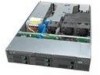
 1
1 65
65 66
66 67
67 68
68 69
69 70
70 71
71 72
72 73
73 74
74 75
75

