Intel SR2625UR Service Guide
Intel SR2625UR - Server System - 0 MB RAM Manual
 |
UPC - 735858206792
View all Intel SR2625UR manuals
Add to My Manuals
Save this manual to your list of manuals |
Intel SR2625UR manual content summary:
- Intel SR2625UR | Service Guide - Page 1
Intel® Server System SR2600UR/ SR2625UR Service Guide A Guide for Technically Qualified Assemblers of Intel® Identified Subassemblies/ Products Intel Order Number E51243-007 - Intel SR2625UR | Service Guide - Page 2
or registered trademarks of Intel Corporation or its subsidiaries in the United States and other countries. * Other names and brands may be claimed as the property of others. Copyright © 2008-2011, Intel Corporation. All Rights Reserved ii Intel® Server System SR2600UR/SR2625UR Service Guide - Intel SR2625UR | Service Guide - Page 3
and using the Intel® Server System SR2600UR/SR2625UR. This manual is written for system technicians who are responsible for troubleshooting, upgrading, and repairing this server system. This document provides reference information, feature information, and step-by-step instructions for adding and - Intel SR2625UR | Service Guide - Page 4
iv Intel® Server System SR2600UR/SR2625UR Service Guide - Intel SR2625UR | Service Guide - Page 5
documento antes de realizar cualquiera de las instrucciones. Vea Intel Server Boards and Server Chassis Safety Information en el Intel® Server Deployment Toolkit 3.0 CD y/o en http://www.intel.com/support/motherboards/server/sb/cs-010770.htm. Intel® Server System SR2600UR/SR2625UR Service Guide v - Intel SR2625UR | Service Guide - Page 6
provide some ESD protection by wearing an antistatic wrist strap attached to chassis ground any unpainted metal surface on your server when handling parts. ESD and handling boards: Always handle boards If your jumpers do not have such a tab, vi Intel® Server System SR2600UR/SR2625UR Service Guide - Intel SR2625UR | Service Guide - Page 7
inside the jumper, causing intermittent problems with the function controlled by that jumper. Take care to grip with, but not squeeze, the pliers or other tool you use to remove a jumper, or you may bend or break the pins on the board. Intel® Server System SR2600UR/SR2625UR Service Guide vii - Intel SR2625UR | Service Guide - Page 8
viii Intel® Server System SR2600UR/SR2625UR Service Guide - Intel SR2625UR | Service Guide - Page 9
/SR2625URBRP (Passive System) Contents ... 2 Additional Information and Software 4 Chapter 2: Server System Features 7 Server System Feature Overview 9 Server System Components 11 Intel® Server System SR2600UR Components 12 Intel® Server System SR2625UR Components 13 Intel® Light-Guided - Intel SR2625UR | Service Guide - Page 10
or Replacing the Processor 59 Installing the Processor 60 Installing the Heatsink 62 Removing the Heatsink 64 Removing the Processor 65 Removing and Installing the Small Air Baffle (Intel® Server System SR2600UR only) ....... 66 x Intel® Server System SR2600UR/SR2625UR Service Guide - Intel SR2625UR | Service Guide - Page 11
RAID Mini-DIMM (Active Systems Only) ...112 Installing the RAID Activation Key and the RAID Mini-DIMM 112 Removing the RAID Activation Key and the RAID Mini-DIMM 113 Installing and Removing the RAID Battery Backup Unit (Active Systems Only 115 Intel® Server System SR2600UR/SR2625UR Service Guide - Intel SR2625UR | Service Guide - Page 12
161 Warranty Information ...161 Appendix E: Regulatory and Certification Information 163 Product Regulatory Compliance 163 Product Safety Compliance 163 Product EMC Compliance - Class A Compliance 164 xii Intel® Server System SR2600UR/SR2625UR Service Guide - Intel SR2625UR | Service Guide - Page 13
Declaration of Conformity (Europe 173 VCCI (Japan) ...173 BSMI (Taiwan) ...173 KCC (Korea) ...174 Regulated Specified Components 174 Appendix F: Installation/Assembly Safety Instructions (ESD 196 Andere Gefahren ...196 Français ...197 Intel® Server System SR2600UR/SR2625UR Service Guide xiii - Intel SR2625UR | Service Guide - Page 14
de alimentación 205 Advertencias el acceso al sistema 206 Advertencias sobre el montaje en bastidor 207 Descarga electrostática (ESD 207 Otros riesgos ...208 xiv Intel® Server System SR2600UR/SR2625UR Service Guide - Intel SR2625UR | Service Guide - Page 15
Card 54 Figure 37. Removing a Full-height Add-In Card 55 Figure 38. Removing the Processor Air Duct 56 Figure 39. Installing the Processor Air Duct 57 Figure 40. Installing the Memory 58 Figure 41. Lifting the Processor Socket Handle 60 Intel® Server System SR2600UR/SR2625UR Service Guide xv - Intel SR2625UR | Service Guide - Page 16
the Protective Socket Cover 61 Figure 44. Removing the Processor Protective Cover 61 Figure 45. Installing the Processor 62 Figure 46. Closing the Load Plate 62 Figure 47 Installing the I/O Expansion Module to the Server System 98 xvi Intel® Server System SR2600UR/SR2625UR Service Guide - Intel SR2625UR | Service Guide - Page 17
131. Removing the Rack Handle 138 Figure 132. Password Clear Jumper 143 Figure 133. BIOS Default Jumper 144 Figure 134. Diagnostic LED Placement Diagram 154 Intel® Server System SR2600UR/SR2625UR Service Guide xvii - Intel SR2625UR | Service Guide - Page 18
xviii Intel® Server System SR2600UR/SR2625UR Service Guide - Intel SR2625UR | Service Guide - Page 19
Table 6. Power Supply Output Capability 145 Table 7. System Environmental Specifications 146 Table 8. POST Progress Code LED Example 153 Table 9. Diagnostic LED POST Code Decoder 154 Table 10. Product Regulatory Compliance Markings 166 Intel® Server System SR2600UR/SR2625UR Service Guide xix - Intel SR2625UR | Service Guide - Page 20
xx Intel® Server System SR2600UR/SR2625UR Service Guide - Intel SR2625UR | Service Guide - Page 21
• Chassis intrusion switch, integrated into the server system riser • Standard control panel, installed in the server system • Active SAS/SATA midplane, installed in the server system • Hot-swap SAS/SATA backplane, installed in the server system Intel® Server System SR2600UR/SR2625UR Service Guide - Intel SR2625UR | Service Guide - Page 22
box (SR2625URLX only) • Rack handles, in the hardware box • Attention document, in the server system product box • Quick Start User's Guide, in the server system product box • Intel® Server Deployment Toolkit 3.0 CD • Intel® System Management Software DVD Intel® Server System SR2600URBRP/SR2625URBRP - Intel SR2625UR | Service Guide - Page 23
(SR2625URBRP only) • Rack handles, in the hardware box • Attention document, in the server system product box • Quick Start User's Guide, in the server system product box • Intel® Server Deployment Toolkit 3.0 CD • Intel® System Management Software DVD Intel® Server System SR2600UR/SR2625UR Service - Intel SR2625UR | Service Guide - Page 24
at: http://www.intel.com/p/en_US/support/highlights/server/s5520ur Intel® Server System SR2600UR Quick Start User's Guide Provided in the product box Intel® Server System SR2625UR Quick Start User's Guide Provided in the product box Accessories or other Intel server products Spares, Parts List and - Intel SR2625UR | Service Guide - Page 25
budget For software to manage your Intel® server Power Budget Analysis Tool Available at: http://www.intel.com/p/en_US/support/highlights/server/s5520ur Intel® System Management Software Available at: http://www.intel.com/go/servermanagement/ Intel® Server System SR2600UR/SR2625UR Service Guide 5 - Intel SR2625UR | Service Guide - Page 26
6 Intel® Server System SR2600UR/SR2625UR Service Guide - Intel SR2625UR | Service Guide - Page 27
/ SR2625UR. This includes illustrations of the products, a list of the server system features, and diagrams showing the location of important components and connections on the server systems. AF002818 Figure 1. Intel® Server System SR2600UR Intel® Server System SR2600UR/SR2625UR Service Guide 7 - Intel SR2625UR | Service Guide - Page 28
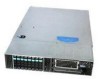
Figure 2. Intel® Server System SR2625UR AF002819 8 Intel® Server System SR2600UR/SR2625UR Service Guide - Intel SR2625UR | Service Guide - Page 29
.htm • Support for 800/1066/1333 MT/s ECC registered (RDIMM) or unbuffered DIMM (UDIMM) DDR3 memory • Twelve DIMMs across six memory channels (three channels per processor) • Intel® 5520 chipset I/O Hub • Intel® 82801Jx I/O Controller Hub Intel® Server System SR2600UR/SR2625UR Service Guide 9 - Intel SR2625UR | Service Guide - Page 30
2.5-inch hard drives or 3.5- inch tape drive • Intel® Embedded Server RAID Technology II with SW RAID levels 0/1/10 • Optional support for SW RAID 5 with activation key • Slimline bay for slimline SATA optical drive • "PCI riser card bracket 10 Intel® Server System SR2600UR/SR2625UR Service Guide - Intel SR2625UR | Service Guide - Page 31
Server System Components This section helps you identify the components of your server system. If you are near the system, you can also use the Quick Reference Label provided on the inside of the chassis cover to assist in identifying components. Intel® Server System SR2600UR/SR2625UR Service Guide - Intel SR2625UR | Service Guide - Page 32
modules) or two 2.5-inch Hard Drives (optional) F. Riser Card Assembly N. Hard Drive Bays G. Integrated Chassis Intrusion Switch O. Slimline Optical Drive Bay H. Processor Air Duct Figure 3. Intel® Server System SR2600UR Components 12 Intel® Server System SR2600UR/SR2625UR Service Guide - Intel SR2625UR | Service Guide - Page 33
L. Flex Bay - Two additional 2.5-inch Hard Drives or Tape Drive (optional) F. Integrated Chassis Intrusion Switch M. Slimline Optical Drive Bay G. Processor Air Duct N. Hard Drive Bays Figure 4. Intel® Server System SR2625UR Components Intel® Server System SR2600UR/SR2625UR Service Guide 13 - Intel SR2625UR | Service Guide - Page 34
. • Fan Fault LEDs on the passive midplane (in the passive system - see Figure 6) or active midplane (in the active system - see Figure 7) help identify failed and failing fans. The fan fault LEDs turn on (amber) if there is a fan fault. 14 Intel® Server System SR2600UR/SR2625UR Service Guide - Intel SR2625UR | Service Guide - Page 35
LED E. CPU 1 Fan Fault LED F. CPU 1 DIMM Fault LEDs G. CPU 2 Fan Fault LED H. Memory 2 Fan Fault LED I. CPU 2 DIMM Fault LEDs J. 5V Standby LED Figure 5. Intel® Light-Guided Diagnostic LEDs - Server Board AF002833 Intel® Server System SR2600UR/SR2625UR Service Guide 15 - Intel SR2625UR | Service Guide - Page 36
LEDs - Passive Midplane D C E B A F AF003042 A. Fan 2 Fault LED B. Fan 3 Fault LED C. Fan 4 Fault LED D. Fan 5 Fault LED E. Fan 6 Fault LED F. Fan 1 Fault LED Figure 7. Intel® Light-Guided Diagnostic LEDs - Active Midplane 16 Intel® Server System SR2600UR/SR2625UR Service Guide - Intel SR2625UR | Service Guide - Page 37
A B AF003002 A. Status LED B. System Identification LED Figure 8. Intel® Light-Guided Diagnostic LEDs - Standard Control Panel Intel® Server System SR2600UR/SR2625UR Service Guide 17 - Intel SR2625UR | Service Guide - Page 38
Server Board Components This section helps you identify the components and connectors on the server board. AB C D E FG H DD I CC J BB AA Z Y X W V U T S R QPO K L NM AF002696 18 Intel® Server System SR2600UR/SR2625UR Service Guide - Intel SR2625UR | Service Guide - Page 39
L. Processor 2 Socket O. Bridge Board Connector (Intel® Server Chassis) R. 2x4 Power Connector U. System 2 Fan Header X. System 1 Fan Header AA. SGPIO Header DD. I/O Module Mezzanine Connector 1 Figure 9. Server Board Connector and Component Locations Intel® Server System SR2600UR/SR2625UR Service - Intel SR2625UR | Service Guide - Page 40
Mode is enabled. These pins should be jumpered on 1-2 for normal system operation. C. BIOS Default (J1E7) If pins 2-3 are jumpered, the BIOS settings are cleared on the next reset. These pins should be jumpered on 1-2 for normal operation. 20 Intel® Server System SR2600UR/SR2625UR Service Guide - Intel SR2625UR | Service Guide - Page 41
user passwords are cleared within five to ten seconds after the system is powered on. These pins should be jumpered on 1-2 for normal system operation. If pins 2-3 are jumpered, the system Bay (Optional) Figure 11. Optional Peripherals Intel® Server System SR2600UR/SR2625UR Service Guide 21 - Intel SR2625UR | Service Guide - Page 42
, sixth hard drive kit, or fixed 2.5inch hard drive kit, use the following order codes: • SATA/SCSI Tape Drive Mounting Kit: ASR2500SATAPE or ADRTAPEKIT • Sixth SAS/SATA Hard Disk Drive (HDD) Kit: ASR2500SIXDRV 22 Intel® Server System SR2600UR/SR2625UR Service Guide - Intel SR2625UR | Service Guide - Page 43
network to which it is connected. Blinking green light indicates network activity. Powers on/off the system. If enabled by an ACPI-compliant operating system, this button functions as a Sleep button and puts the system in an ACPI sleep state. Intel® Server System SR2600UR/SR2625UR Service Guide 23 - Intel SR2625UR | Service Guide - Page 44
to the front of the system. The front and rear video ports cannot be used at the same time. Figure 12. Standard Control Panel Intel® Local Control Panel The following diagram shows the features available on the Intel® Local Control Panel. 24 Intel® Server System SR2600UR/SR2625UR Service Guide - Intel SR2625UR | Service Guide - Page 45
indicates a non-critical condition. No light indicates POST is running or the system is off. Continuous green light indicates a link between the system and the network to which it is connected. Blinking green light indicates network activity. Intel® Server System SR2600UR/SR2625UR Service Guide 25 - Intel SR2625UR | Service Guide - Page 46
47. The order numbers for the bezels are: • ADRBEZBLACK: Black bezel for use with the standard control panel. • ADRLCDBEZEL: Black bezel for use with the Intel® Local Control Panel. 26 Intel® Server System SR2600UR/SR2625UR Service Guide - Intel SR2625UR | Service Guide - Page 47
a maximum ambient temperature of 45°C. Note: The Intel® Server System SR2625UR does not support all SAS or Serial ATA (SATA) hard drives. For a web link to a list of supported hard drives, see "Additional Information and Software" on page 4. Intel® Server System SR2600UR/SR2625UR Service Guide 27 - Intel SR2625UR | Service Guide - Page 48
, see "Installing a Tape Drive" on page 84. For instructions on installing the two fixed 2.5-inch hard drives, see "Installing the 2.5-Inch Fixed Hard Disk Drives" on page 90. Control Panel The Intel® Server System SR2625UR supports the following types of control panels: • Standard Control Panel - Intel SR2625UR | Service Guide - Page 49
Module G. Intel® I/O Expansion Module (Optional) H. Intel® Remote Management Module NIC (Optional) I. NIC 1 J. NIC 2 K. USB 6 L. USB 5 M. DB-9 Serial B Connector N. Video O. RJ-45 Serial A Connector Figure 15. Server System Back Panel Intel® Server System SR2600UR/SR2625UR Service Guide 29 - Intel SR2625UR | Service Guide - Page 50
Back Panel Connectors A B C D E F A. Mouse C. Serial Port B (RJ-45) E. NIC 2 (10/100/1000 Mb) G. USB Port 6 B. Keyboard D. NIC 1 (10/100/1000 Mb) F. Video H. USB Port 5 Figure 16. Back Panel Connectors AF004112 30 Intel® Server System SR2600UR/SR2625UR Service Guide - Intel SR2625UR | Service Guide - Page 51
network connection Network connection in place Transmit/receive activity 10 Mbps connection (if right LED is on or blinking) 100 Mbps connection 1000 Mbps connection Intel® Server System SR2600UR/SR2625UR Service Guide 31 - Intel SR2625UR | Service Guide - Page 52
server board, hot-swap backplane, and control panel. Two midplanes are offered for this system: • Passive SATA/SAS midplane (data cables required) • Active SAS/SATA RAID 6 and 7 are not used in the Intel® Server System SR2600UR/SR2625UR. 32 Intel® Server System SR2600UR/SR2625UR Service Guide - Intel SR2625UR | Service Guide - Page 53
C D E F G H I J L K AF002790 A. Optional RAID Cache Battery Backup Connector B. Midplane Power Connector C. Mini-DIMM Connector D. RAID Activation Key Connector L. Backplane Connectors Figure 18. Active SAS/SATA RAID Midplane Components Intel® Server System SR2600UR/SR2625UR Service Guide - Intel SR2625UR | Service Guide - Page 54
connector found on the backplane. A B C D AF000045 A. Slimline Interposer Card Connector B. USB Floppy Connector C. Control Panel Connector D. SAS/SATA Hot-swap Connectors Figure 19. Hot-Swap SAS/SATA Backplane Components (Front View) 34 Intel® Server System SR2600UR/SR2625UR Service Guide - Intel SR2625UR | Service Guide - Page 55
Connector (for sixth hard drive or tape drive or 2.5-inch fixed drives) B. SAS/SATA Connector (for sixth hard drive or SATA tape drive) C. Power Connector D. Midplane Connectors Figure 20. Hot-Swap SAS/SATA Backplane Components (Rear View) Intel® Server System SR2600UR/SR2625UR Service Guide 35 - Intel SR2625UR | Service Guide - Page 56
drives. The following diagrams show the location for each connector found on the backplane. A B AF002788 A. SAS/SATA Hot-swap Connectors B. Slimline Optical Drive Connector Figure 21. Hot-Swap SAS/SATA Backplane Components (Front View) 36 Intel® Server System SR2600UR/SR2625UR Service Guide - Intel SR2625UR | Service Guide - Page 57
or disable "AHCI Mode" or "Configure SATA as RAID". The Intel® Embedded Server RAID Technology II is enabled by the "Configure SATA as RAID" option. The Intel® Embedded Server RAID Technology II feature provides RAID modes 0, 1, and 10. Intel® Server System SR2600UR/SR2625UR Service Guide 37 - Intel SR2625UR | Service Guide - Page 58
rack, the second system in the second position from the bottom, and so on. For instructions on installing your chassis into a rack, see "Removing and Installing from a Rack" on page 42. These instructions are also included in the rail kit. 38 Intel® Server System SR2600UR/SR2625UR Service Guide - Intel SR2625UR | Service Guide - Page 59
normal operation. Note: If the procedure for servicing a particular component is identical for both Intel® Server System SR2600UR and Intel® Server System SR2625UR, only the Intel® Server System SR2600UR is shown for illlustration purposes. Intel® Server System SR2600UR/SR2625UR Service Guide 39 - Intel SR2625UR | Service Guide - Page 60
Power to Active Midplane Board O Server Board SATA 5 Connector Legend 4 Begin cable connections at the 3 SATA-0 location. 2 1 0 C Server Board O CPU1 F LK D K J H I N G CPU2 M E Figure 23. Cable Routing AF002993 40 Intel® Server System SR2600UR/SR2625UR Service Guide - Intel SR2625UR | Service Guide - Page 61
Fan Connections Use the figures below to determine the proper fan connections. 3 2 1 AF003109 Figure 24. Connecting the Non-redundant Fan Power Cables to the Passive Midplane Board Intel® Server System SR2600UR/SR2625UR Service Guide 41 - Intel SR2625UR | Service Guide - Page 62
allows you to service the server system while installed in a rack. Note: Follow all safety guidelines while removing a system from a rack to avoid injury. Fixed Bracket Rack Mount Removal 1. Disconnect all cables from the back of the system. 42 Intel® Server System SR2600UR/SR2625UR Service Guide - Intel SR2625UR | Service Guide - Page 63
of the chassis with the finger tab facing outward and located closer to the rear of the chassis. 4. Align the holes in the rail with the tabs on the chassis and place the rail against the chassis. 5. screw. If possible, attach at two places. Intel® Server System SR2600UR/SR2625UR Service Guide 43 - Intel SR2625UR | Service Guide - Page 64
each rail. 8. Align the inner rails (attached to the server chassis) with the outer rail assemblies (attached to the rack). 9. Engage the matching rails and slide the server chassis into the rack until the two safety stops lock into position. 44 Intel® Server System SR2600UR/SR2625UR Service Guide - Intel SR2625UR | Service Guide - Page 65
figures. Note the orientation in the figures the control panel is at the right. If you are installing a bezel on your server system, make sure you position it as shown. AF000154 Figure 26. Front Bezel Supporting the Standard Control Panel Intel® Server System SR2600UR/SR2625UR Service Guide 45 - Intel SR2625UR | Service Guide - Page 66
Panel Removing the Front Bezel If your system includes a front bezel, follow these steps to remove the front bezel: 1. Unlock the bezel (if locked). 2. Pull the bezel from the server system. TP02129 Figure 28. Removing the Front Bezel 46 Intel® Server System SR2600UR/SR2625UR Service Guide - Intel SR2625UR | Service Guide - Page 67
: 1. At each end of the bezel, line up the center notch on the bezel with the center guide on the rack handles. 2. Push the bezel onto the front of the server system until it clicks into place. TP02130 Figure 29. Installing the Front Bezel Intel® Server System SR2600UR/SR2625UR Service Guide 47 - Intel SR2625UR | Service Guide - Page 68
letter "A" in Figure 30). 2. While holding in the blue button at the top of the server system in (see letter "B" in Figure 30), slide the top cover back until it stops (see . D A C B AF002954 Figure 30. Removing the Server System Cover 48 Intel® Server System SR2600UR/SR2625UR Service Guide - Intel SR2625UR | Service Guide - Page 69
31). 3. (Optional) Insert the safety screw at the center of the top cover (see letter "B" in Figure 31), if required. B A AF002955 Figure 31. Installing the Server System Cover Intel® Server System SR2600UR/SR2625UR Service Guide 49 - Intel SR2625UR | Service Guide - Page 70
in Figure 33). A A Riser Card Connector B AF002967 Figure 32. Removing PCI Riser Assembly from the Server System 4. Do one of the following: - If you need to add or replace a PCI add-in for another procedure, continue with that procedure. 50 Intel® Server System SR2600UR/SR2625UR Service Guide - Intel SR2625UR | Service Guide - Page 71
the server system back panel slots. The riser cards will seat into the matching sockets on the server board. 4. Connect any cables to add-in cards that require them. See your add-in card documentation for information and add-in card requirements. Intel® Server System SR2600UR/SR2625UR Service Guide - Intel SR2625UR | Service Guide - Page 72
B C Riser Card AF003012 Figure 34. Removing the PCI Riser Card from the Server System (Full-height Side) 6. Install the replacement riser card, if desired. For instructions, see "Installing PCI Riser Card into the Server System" on page 53. 52 Intel® Server System SR2600UR/SR2625UR Service Guide - Intel SR2625UR | Service Guide - Page 73
. 8. Install the PCI add-in card(s), if desired. For instructions, see "Installing a PCI Add-in Card" on page 54. 9. Install the PCI riser assembly into the server system. For instructions, see "Installing the PCI Riser Assembly" on page 51. Intel® Server System SR2600UR/SR2625UR Service Guide 53 - Intel SR2625UR | Service Guide - Page 74
Card To install a PCI add-in card, follow these steps: 1. Remove the PCI riser assembly. For instructions, see "Removing the PCI Riser Assembly" on page 50. 2. Open the rear retention clip by pushing the slots have filler panels installed. 54 Intel® Server System SR2600UR/SR2625UR Service Guide - Intel SR2625UR | Service Guide - Page 75
lock it into place. Note: Make sure that all empty add-in card slots have filler panels installed. 8. Install the PCI riser assembly into the server system. For instructions, see "Installing the PCI Riser Assembly" on page 51. Intel® Server System SR2600UR/SR2625UR Service Guide 55 - Intel SR2625UR | Service Guide - Page 76
the PCI riser assembly. For instructions, see "Removing the PCI Riser Assembly" on page 50. 2. Lift the processor air duct from its location over the two processor sockets. AirPDrouccetssor AF002956 Figure 38. Removing the Processor Air Duct 56 Intel® Server System SR2600UR/SR2625UR Service Guide - Intel SR2625UR | Service Guide - Page 77
To install DIMMs, follow these steps: 1. Remove the PCI riser assembly. For instructions, see "Removing the PCI Riser Assembly" on page 50. 2. Remove the processor air duct. For instructions, see "Removing the Processor Air Duct" on page 56 Intel® Server System SR2600UR/SR2625UR Service Guide 57 - Intel SR2625UR | Service Guide - Page 78
the retaining clips snap into place (see letter "C" in Figure 40). Make sure the clips are firmly in place (see letter "D" in Figure 40). 58 Intel® Server System SR2600UR/SR2625UR Service Guide - Intel SR2625UR | Service Guide - Page 79
the static charge while handling the processor. (2) Avoid moving around unnecessarily. Caution: Protective socket cover needs to be removed for proper cooling of the processor; failure to remove the cover could result in damage to the system. Intel® Server System SR2600UR/SR2625UR Service Guide 59 - Intel SR2625UR | Service Guide - Page 80
processor air duct. For instructions, see "Removing the Processor Air Duct" on page 56 3. Remove the heatsink, if installed. For instructions, see "Removing the Heatsink" on page 64. 4. Locate the processor processor that will not be replaced. 60 Intel® Server System SR2600UR/SR2625UR Service Guide - Intel SR2625UR | Service Guide - Page 81
Removing the Processor Protective Cover 11. Orient the processor with the socket such that the orientation notches on the processor align with the two orientation posts on the socket, and insert the processor into the socket (see Figure 45). Intel® Server System SR2600UR/SR2625UR Service Guide 61 - Intel SR2625UR | Service Guide - Page 82
heatsink so you do not damage the TIM. Note: New unused heatsinks have adequate TIM on the bottom. If you are reusing a heatsink from replacing a processor, make sure there is adequate TIM present on the heatsink to support processor cooling. 62 Intel® Server System SR2600UR/SR2625UR Service Guide - Intel SR2625UR | Service Guide - Page 83
the system. 3. Set the heatsink over the processor, lining up the four captive screws with the four posts surrounding the processor. 4. Flow 1 4 TIM Chassis Front AF002841 Figure 47. Installing the Heatsink (Passive Heatsink Shown) Intel® Server System SR2600UR/SR2625UR Service Guide 63 - Intel SR2625UR | Service Guide - Page 84
to break the seal between the heatsink and the processor. ii. Lift the heatsink from the processor. If it does not pull up easily, twist the heatsink again. Do not force the heatsink from the processor. Doing so could damage the processor. 64 Intel® Server System SR2600UR/SR2625UR Service Guide - Intel SR2625UR | Service Guide - Page 85
41). 6. Open the CPU load plate (see Figure 42). 7. Remove the processor. 8. If you want to replace the processor, see "Installing the Processor" on page 60. Otherwise, install the protective socket cover over the empty processor socket. Intel® Server System SR2600UR/SR2625UR Service Guide 65 - Intel SR2625UR | Service Guide - Page 86
Installing the Small Air Baffle To install the small air baffle, follows these steps: 1. Lower the baffle into the server system and position the baffle over the two standoff locations. 2. Snap the baffle into place as shown in Figure 50. 66 Intel® Server System SR2600UR/SR2625UR Service Guide - Intel SR2625UR | Service Guide - Page 87
the fan baffle. Use the instructions in these sections only when it is indicated as necessary for a component installation process. Always operate your server system with the fan baffle in 51). 3. Pull up on it (see letter "C" in Figure 51). Intel® Server System SR2600UR/SR2625UR Service Guide 67 - Intel SR2625UR | Service Guide - Page 88
A C B AF003021 Figure 51. Removing the Fan Baffle 68 Intel® Server System SR2600UR/SR2625UR Service Guide - Intel SR2625UR | Service Guide - Page 89
the backplane board (see letter "C" in Figure 52 - the arrow is pointing to the hole in the backplane board). C B A Figure 52. Installing the Fan Baffle Intel® Server System SR2600UR/SR2625UR Service Guide AF003022 69 - Intel SR2625UR | Service Guide - Page 90
air baffle. Use the instructions in these sections only when it is indicated as necessary for a component installation process. Always operate your server system with the large air baffle the Quick Reference Label that came with your system. 70 Intel® Server System SR2600UR/SR2625UR Service Guide - Intel SR2625UR | Service Guide - Page 91
the black lever and pull out on the lever to release the hard drive carrier (see letter "A" in Figure 55). 2. Slide the carrier from the server system (see letter "B" in Figure 55). Intel® Server System SR2600UR/SR2625UR Service Guide 71 - Intel SR2625UR | Service Guide - Page 92
antistatic surface. 5. Set any jumpers and/or switches on the drive according to the drive manufacturer's instructions. 6. With the drive circuit-side down, position the connector end of the drive so that it retention device (see Figure 57). 72 Intel® Server System SR2600UR/SR2625UR Service Guide - Intel SR2625UR | Service Guide - Page 93
the server system and push all the way until it stops (see letter "A" in Figure 58). 9. Close the lever to lock the drive assembly into place (see letter "B" in Figure 58). A B AF002946 Figure 58. Install Drive Assembly into the Server System Intel® Server System SR2600UR/SR2625UR Service Guide 73 - Intel SR2625UR | Service Guide - Page 94
possible damage to your server system, do not use older style drive carriers. Note: The server system does not support all hard drives. For a web link to a list of supported hard drives, see "Additional Information and Software" on page 4. 74 Intel® Server System SR2600UR/SR2625UR Service Guide - Intel SR2625UR | Service Guide - Page 95
To install a hot-swap SAS/SATA hard disk drive in Intel® Server System SR2625UR, follow these steps: 1. instructions. 6. With the drive circuit-side down, position the connector end of the drive so that it is facing the rear of the drive carrier. Intel® Server System SR2600UR/SR2625UR Service Guide - Intel SR2625UR | Service Guide - Page 96
a hot-swap SAS/SATA hard disk drive from Intel® Server System SR2625UR, follow these steps: 1. Press in on the green latch at the front of the hard drive carrier. 2. Pull out on the black lever to slide the carrier out from the server system. 76 Intel® Server System SR2600UR/SR2625UR Service Guide - Intel SR2625UR | Service Guide - Page 97
a SAS or SATA system cooling, a filler blank must be installed if you do not install a device at this location. Note: The Intel® Server System SR2600UR also supports the installation of a USB floppy in place of the slimline SATA optical device. Intel® Server System SR2600UR/SR2625UR Service Guide - Intel SR2625UR | Service Guide - Page 98
Internal USB Floppy To install a slimline optical drive or internal USB floppy in Intel® Server System SR2600UR, follow these steps: 1. Remove the empty tray and screw from the Figure 64. Installing the Optical Device into the Drive Tray 78 Intel® Server System SR2600UR/SR2625UR Service Guide - Intel SR2625UR | Service Guide - Page 99
the Interposer Board to the Device Tray 6. Insert the optical device tray assembly into the server system (see letter "A" in Figure 66). 7. Make sure that the back end of the . Installing an Optical Drive Assembly into the Server System Intel® Server System SR2600UR/SR2625UR Service Guide 79 - Intel SR2625UR | Service Guide - Page 100
Drive or Internal USB Floppy To remove a slimline optical drive or internal USB floppy from Intel® Server System SR2600UR, follow these steps: 1. If removing an internal USB floppy, unplug it from "C" in Figure 68) to remove it from the tray. 80 Intel® Server System SR2600UR/SR2625UR Service Guide - Intel SR2625UR | Service Guide - Page 101
5. If no device will be installed in this location, install a filler blank as shown in Figure 69. A AF000155 Figure 69. Installing Filler Blank into the Server System Intel® Server System SR2600UR/SR2625UR Service Guide 81 - Intel SR2625UR | Service Guide - Page 102
Guide to the Optical Drive 2. Insert the optical drive tray assembly into the server system opening and push all the way until it stops (see Figure 66). 3. Make sure that the back end of the device plugs into the matching socket on the backplane. 82 Intel® Server System SR2600UR/SR2625UR Service - Intel SR2625UR | Service Guide - Page 103
from Intel® Server System SR2625UR, follow these steps: 1. Press in on the plastic guide at the rear of the optical drive (see letter "A" in Figure 72) and push forward to unlock and remove the slimline optical drive from the server system. Intel® Server System SR2600UR/SR2625UR Service Guide 83 - Intel SR2625UR | Service Guide - Page 104
. 1. Remove the drive tray from the server system by pressing the blue release lever (see letter "A" in Figure 73) and pushing it forward to release it and then sliding it out from the front of the system (see letter "B" in Figure 73). 84 Intel® Server System SR2600UR/SR2625UR Service Guide - Intel SR2625UR | Service Guide - Page 105
A B AF003029 Figure 73. Removing Drive Tray from the Server System 2. Attach the tape drive to the tape drive carrier kit using the four screws that drive into the combined tape drive bay/sixth drive bay until the carrier clicks into place. Intel® Server System SR2600UR/SR2625UR Service Guide 85 - Intel SR2625UR | Service Guide - Page 106
following: a. Connect the one end of the long SATA cable to the SAS/SATA connector on the server board or SAS/SATA add-in PCI card. b. Install the other end of the long SATA cable to the tape drive and route the cable through the air baffle. 86 Intel® Server System SR2600UR/SR2625UR Service Guide - Intel SR2625UR | Service Guide - Page 107
system by pressing the blue release lever (see letter "A" in Figure 76) and pushing it forward to release it and then sliding it out from the front of the system (see letter "B" in Figure 76. A B Figure 76. Removing the Drive Tray AF003029 Intel® Server System SR2600UR/SR2625UR Service Guide - Intel SR2625UR | Service Guide - Page 108
: If you have an active midplane in your system, do the following: a. Install one end of the power cable to the power connector on the backplane and the opposite end to the power connector on the sixth HDD board (see letter "A" in Figure 79). 88 Intel® Server System SR2600UR/SR2625UR Service Guide - Intel SR2625UR | Service Guide - Page 109
letter "B" in Figure 80) and route the cable through the air baffle (see letter "C" in Figure 80). c. Connect the other end of the cable (labeled SERVER BOARD) to the SATA5 connector on the server board (see letter "D" in Figure 80). Intel® Server System SR2600UR/SR2625UR Service Guide 89 - Intel SR2625UR | Service Guide - Page 110
an add-in card that supports the 2.5-inch solid state hard disk drives. Note: The 2.5-inch fixed hard disk drivers (ASR26XXFXDRV) configured with Intel® Embedded Server RAID Technology II is not compatible with hardware RAID mode by using an 90 Intel® Server System SR2600UR/SR2625UR Service Guide - Intel SR2625UR | Service Guide - Page 111
RAID Activation Key and the RAID Mini-DIMM (Active Systems Only)" on page -111. After purchasing the 2.5-inch fixed hard disk drive kit and the 2.5-inch solid state hard disk drives, use the following instructions that are pre-installed in the Intel® Server System SR2600UR/SR2625UR Service Guide 91 - Intel SR2625UR | Service Guide - Page 112
the 2.5-inch fixed hard disk drive kit as shown in Figure 83. A AF003036 Figure 83. Attaching the 2.5-inch HDD assembly to the drive tray 92 Intel® Server System SR2600UR/SR2625UR Service Guide - Intel SR2625UR | Service Guide - Page 113
cable to the two hard disk drives (see letter "B" in Figure 85). 7. Connect one end of the data cables to the SATA connectors on the server board (see letter "C" in Figure 85) or SAS/SATA connectors on the SAS/SATA add-in PCI card. Intel® Server System SR2600UR/SR2625UR Service Guide 93 - Intel SR2625UR | Service Guide - Page 114
the flex bay, install the empty drive tray into the flex bay (that is, empty slot above drive bay 4) (see letter "C" in Figure 86). 94 Intel® Server System SR2600UR/SR2625UR Service Guide - Intel SR2625UR | Service Guide - Page 115
the other drive bays, install the drive blank into the hard drive carrier. • Install empty hard drive carriers into any remaining empty hard drive bays. Intel® Server System SR2600UR/SR2625UR Service Guide 95 - Intel SR2625UR | Service Guide - Page 116
processor air duct. For instructions, see "Removing the Processor Air Duct" on page 56. 3. Squeeze the sides of the I/O expansion module filler panel(s) to disengage it from the server system module over the server board as shown in Figure 88. 96 Intel® Server System SR2600UR/SR2625UR Service Guide - Intel SR2625UR | Service Guide - Page 117
3. Disconnect the I/O expansion module from the server board connector and the standoffs and remove the module out of the server system (see letter "A" in Figure 89. 4. Remove the standoffs from the server board (see letter "B" in Figure 89). Intel® Server System SR2600UR/SR2625UR Service Guide 97 - Intel SR2625UR | Service Guide - Page 118
Module 3, follow these steps: 1. Remove the PCI riser assembly. For instructions, see "Removing the PCI Riser Assembly" on page 50. 2. Remove the processor air duct. For instructions, see "Removing the Processor Air Duct" on page 56. 98 Intel® Server System SR2600UR/SR2625UR Service Guide - Intel SR2625UR | Service Guide - Page 119
Top View AF002948 Figure 91. Installing the Intel® RMM3 to the bracket 5. Connect one end of the cable (labeled 'RMM3') to the RMM3 connector on the Intel® RMM3 (see Figure 92). Note: Cable connectors are keyed and can only go in one way. Intel® Server System SR2600UR/SR2625UR Service Guide 99 - Intel SR2625UR | Service Guide - Page 120
System 8. Install the processor air duct. For instructions, see "Installing the Processor Air Duct" on page 57. 9. Install the PCI riser assembly into the server system. For instructions, see "Installing the PCI Riser Assembly" on page 51. 100 Intel® Server System SR2600UR/SR2625UR Service Guide - Intel SR2625UR | Service Guide - Page 121
. For instructions, see "Removing the Processor Air Duct" on page 56. 3. Remove screws from the back of the chassis (see letter "A" in Figure 94). 4. Disconnect the Intel® RMM3 from the connector on the server board (see letter "B" in Figure 94) and remove the module out of the server system (see - Intel SR2625UR | Service Guide - Page 122
instructions, see "Removing the Processor Air Duct" on page 56. 3. Disconnect all cables from the midplane board. 4. Remove the fan baffle. For instructions, see "Removing the Fan Baffle" on page 67. 5. Remove the bridge board as follows: 102 Intel® Server System SR2600UR/SR2625UR Service Guide - Intel SR2625UR | Service Guide - Page 123
the fan module. For instructions, see "Replacing a Fan Module" on page 128. 7. Hold the midplane board only by the edges and slide the midplane board in the direction shown to release it from the backplane (see letter "A" in Figure 97). Intel® Server System SR2600UR/SR2625UR Service Guide 103 - Intel SR2625UR | Service Guide - Page 124
the midplane board over the retention pins (see letter "A" in Figure 98). 2. Align the four holes on the midplane with the four standoffs on the chassis and press down uniformly until it clicks into place (see letter "B" in Figure 98). 104 Intel® Server System SR2600UR/SR2625UR Service Guide - Intel SR2625UR | Service Guide - Page 125
into the backplane connector (see letter "C" in Figure 98). A C B C Figure 98. Installing the Midplane into the Server System 4. Connect cables as necessary to the midplane board. 5. Passive midplane only: Do the following: AF002973 Intel® Server System SR2600UR/SR2625UR Service Guide 105 - Intel SR2625UR | Service Guide - Page 126
in a system with an active midplane or when using the SATA connectors on the server board to connect the hard drive SATA cables. 6. Install the fan module. For instructions, see on the midplane and server board (see letter "C" in Figure 100). 106 Intel® Server System SR2600UR/SR2625UR Service Guide - Intel SR2625UR | Service Guide - Page 127
removed before attempting to remove the backplane. 2. Remove all hot-swap drive carriers, regardless of whether or not a drive is installed in the carrier. For instructions, see "Removing a SAS or SATA Hot-swap Hard Disk Intel® Server System SR2600UR/SR2625UR Service Guide 107 - Intel SR2625UR | Service Guide - Page 128
release it (see letter "B" in Figure 102). c. Remove the backplane board from the six hooks and pull out of the system (see letter "C" in Figure 102). A B C AF003110 Figure 102. Removing the Backplane from the Intel® Server System SR2625UR 108 Intel® Server System SR2600UR/SR2625UR Service Guide - Intel SR2625UR | Service Guide - Page 129
For Intel® Server System SR2625UR, do the following: a. Hold the backplane only by the edges. Do not push or pull on any components on the backplane. Set the backplane in place at the front of the server system (see letter "A" in Figure 104). Intel® Server System SR2600UR/SR2625UR Service Guide - Intel SR2625UR | Service Guide - Page 130
carriers. For instructions, see "Installing a SAS or SATA Hot-swap Hard Disk Drive" on page 71. 5. Install the midplane board. For instructions, see "Installing the Midplane Board" on page 105. 6. Connect necessary cables to the backplane. 110 Intel® Server System SR2600UR/SR2625UR Service Guide - Intel SR2625UR | Service Guide - Page 131
RAID Key A Backplane Board not shown for clarity BoMairddplane AF002976 Figure 105. Installing the RAID Activation Key and the RAID Mini-DIMM 6. Install the large air baffle. For instructions, see "Installing the Large Air Baffle" on page 70. Intel® Server System SR2600UR/SR2625UR Service Guide - Intel SR2625UR | Service Guide - Page 132
Key and the RAID Mini DIMM 6. Install the large air baffle. For instructions, see "Installing the Large Air Baffle" on page 70. 7. Install the processor air duct. For instructions, see "Installing the Processor Air Duct" on page 57. 112 Intel® Server System SR2600UR/SR2625UR Service Guide - Intel SR2625UR | Service Guide - Page 133
the matching chassis tabs and slide towards the power supply until it locks into place (see letter "C" in Figure 107). 7. Connect the cable from the rear of the RAID battery backup unit to the midplane board (see letter "D" in Figure 107). Intel® Server System SR2600UR/SR2625UR Service Guide 113 - Intel SR2625UR | Service Guide - Page 134
the cable from the rear of the RAID battery backup unit and the midplane board (see letter "A" in Figure 108). 5. Slide the RAID battery backup unit away from the power supply and lift from the server system (see letter "B" in Figure 108). 114 Intel® Server System SR2600UR/SR2625UR Service Guide - Intel SR2625UR | Service Guide - Page 135
Air Baffle" on page 70. 5. Remove the fan module assembly. For instructions, see "Replacing a Fan Module" on page 128. 6. Remove the I/O expansion module, if installed. For instructions, see "Removing the I/O Expansion Module" on page 98. Intel® Server System SR2600UR/SR2625UR Service Guide 115 - Intel SR2625UR | Service Guide - Page 136
) and lift the server board from the server system (see letter "B" in Figure 109). A B AF002980 Figure 109. Removing the Server Board 12. Install the replacement server board. For instructions, see "Installing the Server Board" on page 119. 116 Intel® Server System SR2600UR/SR2625UR Service Guide - Intel SR2625UR | Service Guide - Page 137
a Fan Module" on page 128. 8. Install the large air baffle. For instructions, see "Installing the Large Air Baffle" on page 70. 9. Install the bridge board. For instructions, see step 6 in "Installing the Midplane Board" on page 105. Intel® Server System SR2600UR/SR2625UR Service Guide 117 - Intel SR2625UR | Service Guide - Page 138
" on page 56. 3. Locate the battery on the server board (see Figure 111). 4. Insert the tip of a small flat bladed screwdriver, or an equivalent, under the tab in the plastic retainer. Gently push down on the screwdriver to lift the battery. 118 Intel® Server System SR2600UR/SR2625UR Service Guide - Intel SR2625UR | Service Guide - Page 139
, and unplug the AC power cord from the system or wall outlet. The power supply can be replaced if it fails or if one of the fans that is integrated into it fails. To replace the power supply, follow these steps: 1. Do one of the following: Intel® Server System SR2600UR/SR2625UR Service Guide 119 - Intel SR2625UR | Service Guide - Page 140
Server System 2. Do one of the following: - Insert the replacement power supply module into the power supply cage and push all the way until it clicks into place. AF000024 Figure 114. Installing Power Supply Module into the Server System 120 Intel® Server System SR2600UR/SR2625UR Service Guide - Intel SR2625UR | Service Guide - Page 141
the server board, backplane, and midplane. 6. Remove the hot-swap power supply/supplies. For instructions, see step 1 in "Replacing the Power Supply" on page 121. 7. Remove the two screws to release the module (see letter "A" in Figure 116). Intel® Server System SR2600UR/SR2625UR Service Guide 121 - Intel SR2625UR | Service Guide - Page 142
Large Air Baffle" on page 70. 14. Install the processor air duct. For instructions, see "Installing the Processor Air Duct" on page 57. 15. Install the PCI riser assembly. For instructions, see "Installing the PCI Riser Assembly" on page 51. 122 Intel® Server System SR2600UR/SR2625UR Service Guide - Intel SR2625UR | Service Guide - Page 143
AF002983 Figure 117. Removing Standard Control Panel Module from the Server System 3. Slide the replacement control panel into the server system (see letter "A" in Figure 118) until it clicks into place (see letter "B" in Figure 118). Intel® Server System SR2600UR/SR2625UR Service Guide 123 - Intel SR2625UR | Service Guide - Page 144
the back side of the backplane. 2. Press the latch at the back of the control panel and push it forward to release it from the system (see letter "A" in Figure 119). 124 Intel® Server System SR2600UR/SR2625UR Service Guide - Intel SR2625UR | Service Guide - Page 145
in Figure 120). Data Cable A USB Cable ControlLPoacnael l B AF003015 Figure 120. Connecting the Control Panel Cables 6. Slide the replacement control panel into the server system (see letter "A" in Figure 121) until it clicks into place. Intel® Server System SR2600UR/SR2625UR Service Guide 125 - Intel SR2625UR | Service Guide - Page 146
70. 4. Remove the fan baffle. For instructions, see "Removing the Fan Baffle" on page 67. 5. Remove the bridge board. For instructions, see step 5 in "Removing the Midplane Board" on page 103. 6. Disconnect the fan cables from the midplane. 126 Intel® Server System SR2600UR/SR2625UR Service Guide - Intel SR2625UR | Service Guide - Page 147
fan module assembly as follows: a. Lower the fan assembly into the chassis (see letter "A" in Figure 123). b. Line up the pins on the chassis floor with the matching holes on the bottom of the fan assembly (see letter "B" in Figure 123). Intel® Server System SR2600UR/SR2625UR Service Guide 127 - Intel SR2625UR | Service Guide - Page 148
cables through the air baffle as necessary. 12. Install the fan baffle. For instructions, see "Installing the Fan Baffle" on page 69. 13. Install the processor air duct. For instructions, see "Installing the Processor Air Duct" on page 57. 128 Intel® Server System SR2600UR/SR2625UR Service Guide - Intel SR2625UR | Service Guide - Page 149
70. 4. Remove the fan baffle. For instructions, see "Removing the Fan Baffle" on page 67. 5. Remove the bridge board. For instructions, see step 5 in "Removing the Midplane Board" on page 103. 6. Disconnect the fan cables from the midplane. Intel® Server System SR2600UR/SR2625UR Service Guide 129 - Intel SR2625UR | Service Guide - Page 150
fan module assembly as follows: a. Lower the fan assembly into the chassis (see letter "A" in Figure 125). b. Line up the pins on the chassis floor with the matching holes on the bottom of the fan assembly (see letter "B" in Figure 125). 130 Intel® Server System SR2600UR/SR2625UR Service Guide - Intel SR2625UR | Service Guide - Page 151
"Installing the Large Air Baffle" on page 70. 12. Install the fan baffle. For instructions, see "Installing the Fan Baffle" on page 69. 13. Install the processor air duct. For instructions, see "Installing the Processor Air Duct" on page 57. Intel® Server System SR2600UR/SR2625UR Service Guide 131 - Intel SR2625UR | Service Guide - Page 152
14. Install the PCI riser assembly. For instructions, see "Installing the PCI Riser Assembly" on page 51. Replacing a System Fan Replacing a Redundant System Fan Note: The fans that are integrated into fan is at the right and pointing down. 132 Intel® Server System SR2600UR/SR2625UR Service Guide - Intel SR2625UR | Service Guide - Page 153
replaced separately. If one of the fans in the power supply fails, the power supply must be replaced. The system fans at the front of the server system can be individually replaced if one of them fails. To replace a fan, follow these steps: Intel® Server System SR2600UR/SR2625UR Service Guide 133 - Intel SR2625UR | Service Guide - Page 154
1. Remove the fixed fan module. For instructions, see steps 1 through 7 in "Replacing a Fixed Fan Module" on page 131. 2. Pull out the plastic tabs on Position the replacement fan so the connector on the fan is at the right and pointing down. 134 Intel® Server System SR2600UR/SR2625UR Service Guide - Intel SR2625UR | Service Guide - Page 155
page 131. Installing and Removing the Rack Handles Installing the Rack Handles Align the rack handle with the two holes on the side of the server system and attach the rack handle to the server system with two screws as shown in Figure 130. Intel® Server System SR2600UR/SR2625UR Service Guide 135 - Intel SR2625UR | Service Guide - Page 156
. Installing the Rack Handle Removing the Rack Handles Remove the two screws holding the rack handle in place, and remove the rack handle from the server system as shown in Figure 131. AF000020 Figure 131. Removing the Rack Handle 136 Intel® Server System SR2600UR/SR2625UR Service Guide - Intel SR2625UR | Service Guide - Page 157
, you might need to restore the BIOS default settings. For instructions, see "Restoring the BIOS Defaults" on page 144". Setup Menus field that contains user-selectable parameters. These parameters can be changed if the user has adequate Intel® Server System SR2600UR/SR2625UR Service Guide 139 - Intel SR2625UR | Service Guide - Page 158
Esc> key is pressed in any major menu, the exit confirmation window is displayed and the user is asked whether changes can be discarded. Setup Defaults - Pressing causes the following pressed without affecting any existing field values. 140 Intel® Server System SR2600UR/SR2625UR Service Guide - Intel SR2625UR | Service Guide - Page 159
to necessary software and instructions. Recording the Current BIOS Settings 1. Boot the computer and press when you see the message: Press Key if you want to run SETUP 2. Write down the current settings in the BIOS Setup program. Intel® Server System SR2600UR/SR2625UR Service Guide 141 - Intel SR2625UR | Service Guide - Page 160
CMOS Checksum error or other problem after reboot. If this happens, shut down the system and boot it again. CMOS system. Do not unplug the power cord. 2. Open the server system. For instructions on removing the system cover, see "Removing the System Intel® Server System SR2600UR/SR2625UR Service Guide - Intel SR2625UR | Service Guide - Page 161
seconds. 6. Move the Password Clear jumper back to the Password Clear Protect position (covering pins 1 and 2). 7. Close the server system. 8. Power up the server. The password is now cleared and can be reset by going into the BIOS setup. Intel® Server System SR2600UR/SR2625UR Service Guide 143 - Intel SR2625UR | Service Guide - Page 162
five seconds. 6. Return the BIOS Default jumper to the normal position (covering pins 1 and 2). 7. Close the server system. 8. Power up the system. The BIOS defaults settings are now restored and can be reset by going into the BIOS setup. 144 Intel® Server System SR2600UR/SR2625UR Service Guide - Intel SR2625UR | Service Guide - Page 163
total wattage of 750 Watts Table 6. Power Supply Output Capability Voltage Minimum OCP Limits Maximum OCP Limits +3.3 V +5.0 V 110% (= 26.4 A) 110% (= 33 A) 150% (= 36 A) 150% (= 45 A) Intel® Server System SR2600UR/SR2625UR Service Guide 145 - Intel SR2625UR | Service Guide - Page 164
Packaged Unpackaged Vibration Unpackaged Acoustic noise Electrostatic discharge (ESD) System Cooling Requirement in BTU/Hr -40°C to 70°C. (23 +/- 2°C). +/-12 KV except I/O port +/- 8 KV per Intel Environment test specification. 2550 BTU/Hr 146 Intel® Server System SR2600UR/SR2625UR Service Guide - Intel SR2625UR | Service Guide - Page 165
System BIOS Version: Intel® Remote Management Module Firmware Version (if applicable): Intel® Management Module BMC Revision (if applicable) : BMC/mBMC Version: FRU/SDR Version: HSC Version: Has the latest BIOS been tried? (Yes/No): Intel® Server System SR2600UR/SR2625UR Service Guide 147 - Intel SR2625UR | Service Guide - Page 166
1 Processor 2 Processor 3 Processor 4 Type Speed sSpec Thermal Solution Thermal solution (Heatsink) examples: (1U, Passive w/air ducting, Active w/fan, etc Memory: Manufacturer Part Number DRAM Part Number On Intel tested list? 148 Intel® Server System SR2600UR/SR2625UR Service Guide - Intel SR2625UR | Service Guide - Page 167
(Example: RedHat* Enterprise Linux, Microsoft* Windows* Server 2003, Service pack 1, OEM CD): Manufacturer: Version: Language version (English, Arabic, Chinese (Simplified)): Service Pack Level or Kernel Revision: Distribution (OEM/Retail Intel® Server System SR2600UR/SR2625UR Service Guide 149 - Intel SR2625UR | Service Guide - Page 168
RAID driver been tried? (Yes/No): RAID volumes configuration (disks & RAID level): RAID volume use (Boot device/Data Volume): Is BBU (Battery Backup Unit) installed? (Yes/No): BBU part number Detailed description of issue: Troubleshooting tried: 150 Intel® Server System SR2600UR/SR2625UR Service - Intel SR2625UR | Service Guide - Page 169
a brief description below. Have you returned systems or components to your place of purchase because of this issue? If yes, please provide a brief description below. *All other brands and names are property of their respective owners. Intel® Server System SR2600UR/SR2625UR Service Guide 151 - Intel SR2625UR | Service Guide - Page 170
152 Intel® Server System SR2600UR/SR2625UR Service Guide - Intel SR2625UR | Service Guide - Page 171
POST Code Diagnostic LEDs found on the back edge of the server board. To assist in troubleshooting a system hang during the POST process, the Diagnostic LEDs can be used OFF ON OFF ON ON OFF OFF 1 0 1 0 1 1 0 0 Result Ah Ch Intel® Server System SR2600UR/SR2625UR Service Guide 153 - Intel SR2625UR | Service Guide - Page 172
the system, or SPD bad so no memory could be detected O O O X O X OX Channel Training Error: DQ/DQS training failed on a channel during memory channel initialization. O OO X O X OO Memory Test Error: memory failed Hardware BIST. 154 Intel® Server System SR2600UR/SR2625UR Service Guide - Intel SR2625UR | Service Guide - Page 173
-on initialization of the host processor (bootstrap processor) X X X OX XXO Host processor cache initialization (including AP) X X X O X X OX Starting application processor initialization X X X OX X OO SMM initialization Intel® Server System SR2600UR/SR2625UR Service Guide 155 - Intel SR2625UR | Service Guide - Page 174
X O X O X OOX Reserved for PCI bus X OX OX OOO Reserved for PCI bus 0x58h 0x59h X O X O O XXX Resetting USB bus X OX O O XXO Reserved for USB devices 156 Intel® Server System SR2600UR/SR2625UR Service Guide - Intel SR2625UR | Service Guide - Page 175
Disabling the keyboard X X O X X OX Detecting the presence of the keyboard X X OX X OO Enabling the keyboard X X O X OX X Clearing keyboard input buffer X X OX OX O Instructing keyboard controller to run Self Test (PS2 only) Intel® Server System SR2600UR/SR2625UR Service Guide 157 - Intel SR2625UR | Service Guide - Page 176
device selection 2 O OX OX X OO Trying to boot device selection 3 O O X O X OX X Trying to boot device selection 4 O OX OX OX O Trying to boot device selection 5 158 Intel® Server System SR2600UR/SR2625UR Service Guide - Intel SR2625UR | Service Guide - Page 177
beep code) 0xE4h O 0xE5h O 0xE6h O DXE Drivers O O X X OX X Entered EFI driver execution (DXE) phase OOX X OX O Started dispatching drivers O O X X OOX Started connecting drivers 0xE7h O OOX O OX O Waiting for user input Intel® Server System SR2600UR/SR2625UR Service Guide 159 - Intel SR2625UR | Service Guide - Page 178
system to reset (ResetSystem ( ) has been called) 0x30h 0x31h 0x34h 0x35h 0x3Fh X X O O X XXX Crisis recovery has been initiated because of a user crisis recovery capsule X X O O O OOO Unable to complete crisis recovery capsule 160 Intel® Server System SR2600UR/SR2625UR Service Guide - Intel SR2625UR | Service Guide - Page 179
/. Note: You will need to log in to the Reseller site to obtain the 24x7 number. Warranty Information To obtain warranty information, visit the following Intel web site: http://www.intel.com/support/motherboards/server/sb/CS-010807.htm. Intel® Server System SR2600UR/SR2625UR Service Guide 161 - Intel SR2625UR | Service Guide - Page 180
162 Intel® Server System SR2600UR/SR2625UR Service Guide - Intel SR2625UR | Service Guide - Page 181
regulatory compliance, you must adhere to the assembly instructions in this guide to ensure and maintain compliance with existing product & Report, IEC60950 (report to include all country national deviations) • GS Certification (Germany) Intel® Server System SR2600UR/SR2625UR Service Guide 163 - Intel SR2625UR | Service Guide - Page 182
) • BSMI CNS13438 Emissions (Taiwan) • GOST R 29216-91 Emissions (Russia) • GOST R 50628-95 Immunity (Russia) • Belarus Certification (Belarus) • Ukraine Certification (Ukraine) • KCC Certification (EMI) (Korea) 164 Intel® Server System SR2600UR/SR2625UR Service Guide - Intel SR2625UR | Service Guide - Page 183
(Russia) • Belarus Certification/Certification (Belarus) • KCC Certification (Korea) • IRAM Certification (Argentina) • Ecology Declaration (International) • China RoHS Environmental Friendly Use Period • Packaging & Product Recycling Marks Intel® Server System SR2600UR/SR2625UR Service Guide 165 - Intel SR2625UR | Service Guide - Page 184
Intel Server Chassis product if provided with the following regulatory and safety markings. In the event there is no room for a marking(s) on the chassis, the information is provided here in this guide A) Canada VCCI Marking (Class A) Japan 166 Intel® Server System SR2600UR/SR2625UR Service Guide - Intel SR2625UR | Service Guide - Page 185
Belarus Safety Compliance Mark Belarus Waste of Electronic and Electrical Equipment Recycling Mark Europe China Restriction of Hazardous Substance Environmental Friendly Use Period Mark China Intel® Server System SR2600UR/SR2625UR Service Guide 167 - Intel SR2625UR | Service Guide - Page 186
/ perchlorate This notice is required by California Code of Regulations, Title 22, Division 4.5, and Chapter 33: Best Management Practices for Perchlorate Materials. This product may include a battery which contains Perchlorate material. 168 Intel® Server System SR2600UR/SR2625UR Service Guide - Intel SR2625UR | Service Guide - Page 187
the risk of electrical shock, disconnect (2) two power supply cords before servicing. Simplified Chinese: Traditional Chinese: Nordic Countries Safety Connection to Proper Ground to a properly earth grounded outlet." Stand-by power Intel® Server System SR2600UR/SR2625UR Service Guide 169 - Intel SR2625UR | Service Guide - Page 188
must be anchored to an unmovable support to prevent it from falling over when one or more servers are extended in front of the of problems in your server. Ventilation: The equipment rack must provide sufficient airflow to the front of the server to Intel® Server System SR2600UR/SR2625UR Service Guide - Intel SR2625UR | Service Guide - Page 189
that plug into the AC receptacle on the server must be an approved IEC (International Electrotechnical Commission) 320, sheet C13, type female connector. • Cord length and flexibility: Cords must be less than 4.5 meters (14.76 feet) long. Intel® Server System SR2600UR/SR2625UR Service Guide 171 - Intel SR2625UR | Service Guide - Page 190
performance of this product, contact: Intel Corporation 5200 N.E. Elam Young Parkway used in accordance with the instructions, may cause harmful interference turning the equipment off and on, the user is encouraged to try to correct the Intel® Server System SR2600UR/SR2625UR Service Guide - Intel SR2625UR | Service Guide - Page 191
003 of the Canadian Department of Communications. CE Declaration of Conformity (Europe) This product has been instruction manual. BSMI (Taiwan) The BSMI Certification Marking and EMC warning is located on the outside rear area of the product. Intel® Server System SR2600UR/SR2625UR Service Guide - Intel SR2625UR | Service Guide - Page 192
Devices: must be UL recognized or UL listed accessory and TUV or VDE Certificationd. Maximum power rating of any one device is 19 watts. Total server configuration is not to exceed the maximum loading conditions of the power supply. 174 Intel® Server System SR2600UR/SR2625UR Service Guide - Intel SR2625UR | Service Guide - Page 193
some electrostatic discharge (ESD) protection by wearing an antistatic wrist strap attached to chassis ground of the system-any unpainted metal surface-when handling components. 6. Do not operate the system with the chassis covers removed. Intel® Server System SR2600UR/SR2625UR Service Guide 175 - Intel SR2625UR | Service Guide - Page 194
reinstall the chassis covers before turning on the system. Operating the system without the covers in place can damage system parts. Dispose of used batteries according to manufacturer's instructions. The system is designed to operate in a typical Intel® Server System SR2600UR/SR2625UR Service Guide - Intel SR2625UR | Service Guide - Page 195
. 5. Tragen Sie ein geerdetes Antistatik Gelenkband, um elektrostatische Ladungen (ESD) über blanke Metallstellen bei der Handhabung der Komponenten zu vermeiden. 6. Schalten Sie das System niemals ohne ordnungsgemäß montiertes Gehäuse ein. Intel® Server System SR2600UR/SR2625UR Service Guide 177 - Intel SR2625UR | Service Guide - Page 196
anzubringen: 1. Vergewissern Sie sich, daß Sie keine Werkzeuge oder Teile im Innern des Systems zurückgelassen haben. 2. Überprüfen Sie alle Kabel, Zusatzkarten und andere Komponenten Batterien den Anweisungen des Herstellers entsprechend. 178 Intel® Server System SR2600UR/SR2625UR Service Guide - Intel SR2625UR | Service Guide - Page 197
câble d'alimentation de sa prise. C'est le câble d'alimentation qui est considéré comme le moyen de se déconnecter du CA. La prise à laquelle le système est branché doit se situer à proximité de l'équipement et être facilement accessible. Intel® Server System SR2600UR/SR2625UR Service Guide 179 - Intel SR2625UR | Service Guide - Page 198
a été sous tension. Faites également attention aux broches aiguës des cartes et aux bords tranchants du capot. Nous vous recommandons l'usage de gants de protection. 180 Intel® Server System SR2600UR/SR2625UR Service Guide - Intel SR2625UR | Service Guide - Page 199
type ou d'un type équivalent recommandé par le fabricant. Disposez des piles usées selon les instructions du fabricant. Le système a été conçu pour fonctionner dans un cadre de travail normal. ón de corriente alterna que tenga el producto Intel® Server System SR2600UR/SR2625UR Service Guide 181 - Intel SR2625UR | Service Guide - Page 200
sistema y bloquéelo para impedir que pueda accederse al mismo sin autorización. 5. Conecte todos los cables externos y los cables de alimentación CA al sistema. 182 Intel® Server System SR2600UR/SR2625UR Service Guide - Intel SR2625UR | Service Guide - Page 201
. Rivolgersi ad un tecnico specializzato per la riparazione dei componenti dell'alimentazione di questo prodotto. È possibile che il prodotto disponga di più fonti di alimentazione. Intel® Server System SR2600UR/SR2625UR Service Guide 183 - Intel SR2625UR | Service Guide - Page 202
e chiudere a chiave il lucchetto sul retro del sistema per impedire l'accesso non autorizzato al sistema. 5. Ricollegare tutti i cavi esterni e le prolunghe AC del sistema. 184 Intel® Server System SR2600UR/SR2625UR Service Guide - Intel SR2625UR | Service Guide - Page 203
di una presa a muro correttamente installata. • "Dotata di spazio sufficiente ad accedere ai cavi di alimentazione, i quali rappresentano il mezzo principale di scollegamento del sistema. Intel® Server System SR2600UR/SR2625UR Service Guide 185 - Intel SR2625UR | Service Guide - Page 204
186 Intel® Server System SR2600UR/SR2625UR Service Guide - Intel SR2625UR | Service Guide - Page 205
if the WARNING is ignored. Indicates potential hazard if indicated information is ignored. Indicates shock hazards that result in serious injury or death if safety instructions are not followed. Indicates hot components or surfaces. Intel® Server System SR2600UR/SR2625UR Service Guide 187 - Intel SR2625UR | Service Guide - Page 206
regions that are susceptible to electrical storms, we recommend you plug your system into a surge suppresser and disconnect telecommunication lines to your modem during an weight for easier handling, remove any easily detachable components. 188 Intel® Server System SR2600UR/SR2625UR Service Guide - Intel SR2625UR | Service Guide - Page 207
. Your system may use more than one AC power cord. Make sure all AC power cords are unplugged. Make sure the AC power cord(s) is/are unplugged before you open the chassis, or add -outlet(s) that is /are provided with a suitable earth ground. Intel® Server System SR2600UR/SR2625UR Service Guide 189 - Intel SR2625UR | Service Guide - Page 208
, and it must be labeled as controlling power to the entire unit, not just to the server(s). To avoid risk of potential electric shock, a proper safety ground must be implemented for the rack and each piece of equipment installed in it. 190 Intel® Server System SR2600UR/SR2625UR Service Guide - Intel SR2625UR | Service Guide - Page 209
system. • Check that cables, add-in boards, and other components are properly installed. • Attach the covers to the chassis according to the product instructions. devices have are not user serviceable • Return to manufacturer for servicing Intel® Server System SR2600UR/SR2625UR Service Guide 191 - Intel SR2625UR | Service Guide - Page 210
hin, der bei Nichtbeachtung der Sicherheitshinweise zu schweren oder tödlichen Verletzungen führen kann. Weist auf Verbrennungsgefahr an heißen Bauteilen bzw. Oberflächen hin. 192 Intel® Server System SR2600UR/SR2625UR Service Guide - Intel SR2625UR | Service Guide - Page 211
äte erzeugt werden. • In gewittergefährdeten Gebieten sollten Sie das System an einen Überspannungsschutz anschließen und bei einem Gewitter die Telekommunikationskabel lassen, um das Gewicht zu reduzieren und die Handhabung zu erleichtern. Intel® Server System SR2600UR/SR2625UR Service Guide 193 - Intel SR2625UR | Service Guide - Page 212
vom Stromnetz. Die Steckdose muß in der Nähe der Anlage angebracht und gut erreichbar sein. • Netzkabel müssen an eine ordnungsgemäß geerdete Steckdose angeschlossen sein. 194 Intel® Server System SR2600UR/SR2625UR Service Guide - Intel SR2625UR | Service Guide - Page 213
vor, und bauen Sie das schwerste Gerät an der untersten Position im Rack ein. Ziehen Sie jeweils immer nur ein Gerät aus dem Rack heraus. Intel® Server System SR2600UR/SR2625UR Service Guide 195 - Intel SR2625UR | Service Guide - Page 214
. Die Inbetriebnahme des Systems ohne Abdeckung kann zur Beschädigung von Systemkomponenten führen. So bringen Sie die Abdeckung wieder an: • Vergewissern Sie sich zunächst, daß Sie keine Werkzeuge oder Teile im Gehäuse vergessen haben. 196 Intel® Server System SR2600UR/SR2625UR Service Guide - Intel SR2625UR | Service Guide - Page 215
uniquement par des techniciens qualifiés. Vous devez suivre les informations de ce guide et les instructions d'assemblage des manuels de serveur pour vérifier et maintenir la conformité et peuvent figurer sur le produit ou sur son emballage. Intel® Server System SR2600UR/SR2625UR Service Guide 197 - Intel SR2625UR | Service Guide - Page 216
soleil et les radiateurs. • À l'écart des sources de vibration ou des chocs physiques. • Isolé des champs électromagnétiques importants produits par des appareils électriques. 198 Intel® Server System SR2600UR/SR2625UR Service Guide - Intel SR2625UR | Service Guide - Page 217
ou de supprimer un composant non connectable à chaud. Les alimentations de certains serveurs Intel sont munies de doubles fusibles pôle/neutre: veuillez observer les précautions d'usage alimentation. L'intérieur de celui-ci est soumis à des Intel® Server System SR2600UR/SR2625UR Service Guide 199 - Intel SR2625UR | Service Guide - Page 218
Les cordons d'alimentation doivent répondre aux critères suivants : - Le cordon d'alimentation doit supporter une intensité supérieure à celle indiquée sur le produit. - Le cordon d'alimentation communication qui sont connectés au système. 200 Intel® Server System SR2600UR/SR2625UR Service Guide - Intel SR2625UR | Service Guide - Page 219
montage en rack Le rack doit être fixé à un support inamovible pour éviter qu'il ne bascule lors de l'extension quipement. Le rack doit être installé conformément aux instructions du fabricant. Installez les équipements dans le rack en partant Intel® Server System SR2600UR/SR2625UR Service Guide 201 - Intel SR2625UR | Service Guide - Page 220
système. • Vérifiez que les câbles, les cartes d'extension et les autres composants sont correctement installés. • Fixez les panneaux au châssis en suivant les instructions du produit. 202 Intel® Server System SR2600UR/SR2625UR Service Guide - Intel SR2625UR | Service Guide - Page 221
irse a las directrices de esta guía y a las instrucciones de montaje de los manuales del servidor para asegurar y mantener el cumplimiento con las certificaciones y homologaciones existentes de graves si no se tiene en cuenta la ADVERTENCIA. Intel® Server System SR2600UR/SR2625UR Service Guide 203 - Intel SR2625UR | Service Guide - Page 222
conectada a tierra. • Provista de espacio suficiente para acceder a los cables de la fuente de alimentación ya que constituyen la desconexión principal de la alimentación. 204 Intel® Server System SR2600UR/SR2625UR Service Guide - Intel SR2625UR | Service Guide - Page 223
conexión en funcionamiento. Algunas fuentes de alimentación de electricidad de los servidores de Intel utilizan el polo neutral del fuselaje. Para evitar riesgos de choques electricos use adquiera alguno cuyo uso esté aprobado en su país. Intel® Server System SR2600UR/SR2625UR Service Guide 205 - Intel SR2625UR | Service Guide - Page 224
para repararla. • Apague el servidor y desconecte todos los cables de alimentación antes de agregar o reemplazar cualquier componente que no es de conexión en funcionamiento. 206 Intel® Server System SR2600UR/SR2625UR Service Guide - Intel SR2625UR | Service Guide - Page 225
y otros componentes. Recomendamos que realice todos los procedimientos en una estación de trabajo protegida contra descargas electrostáticas. En caso de que no haya una Intel® Server System SR2600UR/SR2625UR Service Guide 207 - Intel SR2625UR | Service Guide - Page 226
dentro del sistema. • Compruebe que los cables, tarjetas adicionales y otros componentes están instalados correctamente. • Sujete las cubiertas a la carcasa siguiendo las instrucciones del producto. 208 Intel® Server System SR2600UR/SR2625UR Service Guide - Intel SR2625UR | Service Guide - Page 227
caja de ningún periférico o dispositivo láser • Los periféricos o dispositivos láser no pueden ser reparados por el usuario • Haga que el fabricante los repare Intel® Server System SR2600UR/SR2625UR Service Guide 209 - Intel SR2625UR | Service Guide - Page 228
210 Intel® Server System SR2600UR/SR2625UR Service Guide
-
 1
1 -
 2
2 -
 3
3 -
 4
4 -
 5
5 -
 6
6 -
 7
7 -
8
-
9
-
10
-
11
-
12
-
13
-
14
-
15
-
16
-
17
-
18
-
19
-
20
-
21
-
22
-
23
-
24
-
25
-
26
-
27
-
28
-
29
-
30
-
31
-
32
-
33
-
34
-
35
-
36
-
37
-
38
-
39
-
40
-
41
-
42
-
43
-
44
-
45
-
46
-
47
-
48
-
49
-
50
-
51
-
52
-
53
-
54
-
55
-
56
-
57
-
58
-
59
-
60
-
61
-
62
-
63
-
64
-
65
-
66
-
67
-
68
-
69
-
70
-
71
-
72
-
73
-
74
-
75
-
76
-
77
-
78
-
79
-
80
-
81
-
82
-
83
-
84
-
85
-
86
-
87
-
88
-
89
-
90
-
91
-
92
-
93
-
94
-
95
-
96
-
97
-
98
-
99
-
100
-
101
-
102
-
103
-
104
-
105
-
106
-
107
-
108
-
109
-
110
-
111
-
112
-
113
-
114
-
115
-
116
-
117
-
118
-
119
-
120
-
121
-
122
-
123
-
124
-
125
-
126
-
127
-
128
-
129
-
130
-
131
-
132
-
133
-
134
-
135
-
136
-
137
-
138
-
139
-
140
-
141
-
142
-
143
-
144
-
145
-
146
-
147
-
148
-
149
-
150
-
151
-
152
-
153
-
154
-
155
-
156
-
157
-
158
-
159
-
160
-
161
-
162
-
163
-
164
-
165
-
166
-
167
-
168
-
169
-
170
-
171
-
172
-
173
-
174
-
175
-
176
-
177
-
178
-
179
-
180
-
181
-
182
-
183
-
184
-
185
-
186
-
187
-
188
-
189
-
190
-
191
-
192
-
193
-
194
-
195
-
196
-
197
-
198
-
199
-
200
-
201
-
202
-
203
-
204
-
205
-
206
-
207
-
208
-
209
-
210
-
211
-
212
-
213
-
214
-
215
-
216
-
217
-
218
-
219
-
220
-
221
-
222
-
223
-
224
-
225
-
226
-
227
-
228
 |
 |

Intel
®
Server System SR2600UR/
SR2625UR Service Guide
A Guide for Technically Qualified Assemblers of Intel
®
Identified Subassemblies/
Products
Intel Order Number E51243-007