Invacare M51P Owners Manual - Page 53
Standard Seat
 |
View all Invacare M51P manuals
Add to My Manuals
Save this manual to your list of manuals |
Page 53 highlights
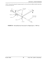
SECTION 9-FRONT RIGGINGS Standard Seat NOTE: For this procedure, refer to FIGURE 9.7 on page 54. NOTE: When adjusting the telescoping front rigging support depth, ensure the footplate does not interfere with the caster wheel rotation. NOTE: Telescoping front rigging supports may be extended up to 2‐inches from the wheelchair frame in 1‐inch increments. This adjustment does not affect seat depth. NOTE: When installing the front riggings support tubes, ensure that the hinge pins are on the outside of the chair facing away from the seat frame. 1. Remove the seat. Refer to Removing/Installing the Seat Assembly on page 35. 2. Remove the two socket bolts and locknuts that secure telescoping front rigging support to the seat frame. 3. Perform one of the following: • Adjusting ‐ Align the appropriate mounting hole of the telescoping front rigging support with the front mounting hole in the seat frame tubes to achieve the desired depth as shown in FIGURE 9.7. • Replacing ‐ i. Remove the existing telescoping front rigging support from the wheelchair frame. ii. Insert the new telescoping front rigging support into the seat frame. iii. Align the appropriate mounting hole of the telescoping front rigging support with the front mounting hole in the seat frame tubes to achieve the desired depth as shown in FIGURE 9.7. NOTE: The footplate will be on the inside of the wheelchair when locked in place. 4. Using the two socket bolts and locknuts, secure the telescoping front rigging support to the seat frame as shown in FIGURE 9.7. 5. If necessary, repeat STEPS 2‐4 on remaining telescoping front rigging support. 6. Reinstall the seat. Refer to Removing/Installing the Seat Assembly on page 35. Part No 1125085 53 Pronto® M51™and M61™with SureStep®
-
 1
1 -
2
-
3
-
4
-
5
-
6
-
7
-
8
-
9
-
10
-
11
-
12
-
13
-
14
-
15
-
16
-
17
-
18
-
19
-
20
-
21
-
22
-
23
-
24
-
25
-
26
-
27
-
28
-
29
-
30
-
31
-
32
-
33
-
34
-
35
-
36
-
37
-
38
-
39
-
40
-
41
-
42
-
43
-
44
-
45
-
46
-
47
-
 48
48 -
 49
49 -
 50
50 -
 51
51 -
 52
52 -
 53
53 -
 54
54 -
 55
55 -
 56
56 -
 57
57 -
 58
58 -
59
-
60
-
61
-
62
-
63
-
64
-
65
-
66
-
67
-
68
-
69
-
70
-
71
-
72
-
73
-
74
-
75
-
76
-
77
-
78
-
79
-
80
 |
 |
