Invacare TDXSP Owners Manual - Page 45
Joystick, Charger/Programming Input, Information Gauge Display, Service Indicator - tdx sp fault codes
 |
View all Invacare TDXSP manuals
Add to My Manuals
Save this manual to your list of manuals |
Page 45 highlights
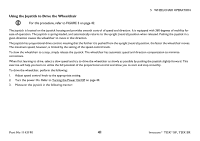
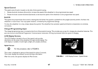
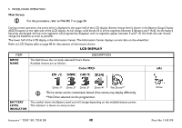
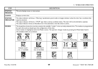
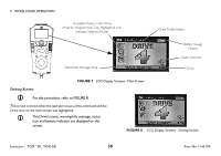
5 WHEELCHAIR OPERATION Joystick The joystick has proportional drive control, meaning that the further the joystick is pushed from the upright (neutral) position, the faster the wheelchair or seat moves. Your top speed, however, is limited by the programmed settings. To slow the wheelchair to a stop, simply release the joystick. The wheelchair has automatic speed and direction compensation to minimize corrections. Charger/Programming Input The charger/programming input is located at the front of the joystick housing. This provides easy access for charging the wheelchair batteries. This port also serves as the Remote Programmer Communication connection. Driving is prevented while the system is charging. Information Gauge Display The information gauge display is located on the front of the joystick housing and provides the following information to the user on the status of the wheelchair: 1. Power is On. 2. True state-of-battery-charge, including notification of when the battery requires charging: A. GREEN LEDs are lit, indicating well charged batteries. B. AMBER LEDs are lit, indicating batteries are moderately charged. Recharge batteries before taking a long trip. C. RED LEDs are lit, indicating batteries are running out of charge. Recharge batteries as soon as possible. The Information Gauge display also serves as a system diagnostic device when a fault is detected by the control module. A specific number of flashes of the LEDs indicate the type of fault detected. Refer to Information Gauge Display Diagnostics on page 100 for the diagnostic indications of the wheelchair status. Service Indicator The AMBER service indicator will light when an error or fault occurs. Refer to Service Indicator Light Diagnostics on page 101 for a listing of the flash codes and what they indicate. Part No 1143190 45 Invacare® TDX®SP, TDX SR
-
 1
1 -
2
-
3
-
4
-
5
-
6
-
7
-
8
-
9
-
10
-
11
-
12
-
13
-
14
-
15
-
16
-
17
-
18
-
19
-
20
-
21
-
22
-
23
-
24
-
25
-
26
-
27
-
28
-
29
-
30
-
31
-
32
-
33
-
34
-
35
-
36
-
37
-
38
-
39
-
 40
40 -
 41
41 -
 42
42 -
 43
43 -
 44
44 -
 45
45 -
 46
46 -
 47
47 -
 48
48 -
 49
49 -
 50
50 -
51
-
52
-
53
-
54
-
55
-
56
-
57
-
58
-
59
-
60
-
61
-
62
-
63
-
64
-
65
-
66
-
67
-
68
-
69
-
70
-
71
-
72
-
73
-
74
-
75
-
76
-
77
-
78
-
79
-
80
-
81
-
82
-
83
-
84
-
85
-
86
-
87
-
88
-
89
-
90
-
91
-
92
-
93
-
94
-
95
-
96
-
97
-
98
-
99
-
100
-
101
-
102
-
103
-
104
-
105
-
106
-
107
-
108
 |
 |
