Invacare TDXSP Owners Manual - Page 46
and nXc Joystick Switches and Indicators, On/Off - Drive Select Toggle Switch CMPJ+ Joystick
 |
View all Invacare TDXSP manuals
Add to My Manuals
Save this manual to your list of manuals |
Page 46 highlights
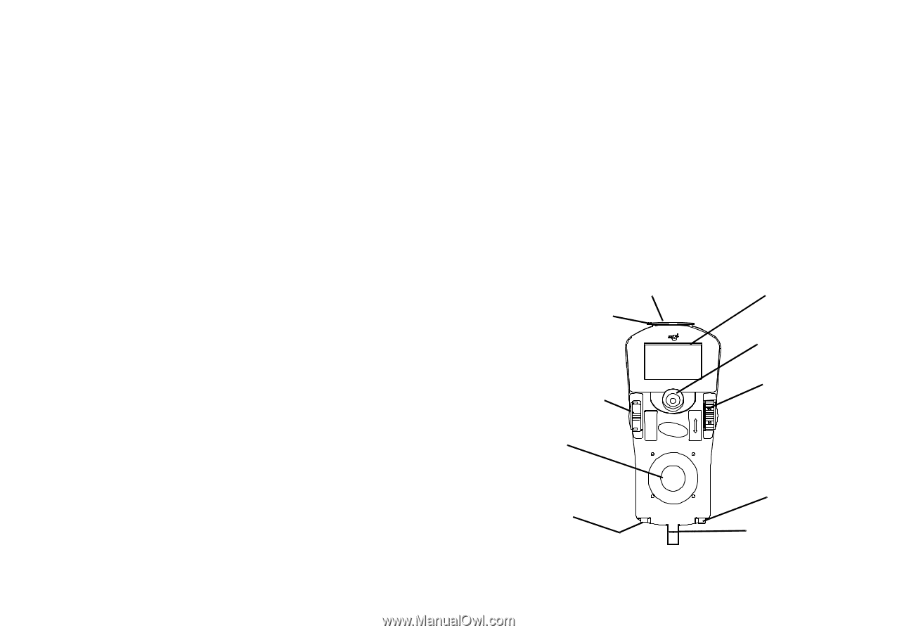
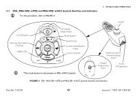
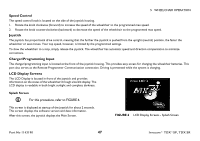
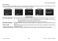
5 WHEELCHAIR OPERATION 5.4 CMPJ+ and nXc Joystick Switches and Indicators For this procedure, refer to FIGURE 5. On/Off - Drive Select Toggle Switch (CMPJ+ Joystick) The drive select toggle switch is located on the left side, below the LCD. The drive select position is momentary, meaning that it will return to the neutral position after a selection is made. This switch allows the operator to select the type of operation or performance which best suits a particular control need or situation. The DRIVE 1 program uses performance values which are independent of those used for the DRIVE 2 or 3 or 4 program. As an example, an operator may have a control need for spasticity in the morning and a very different need in the afternoon. DRIVE 1 can be programmed for higher speeds and quicker response while DRIVE 2 can be programmed for slower speeds and less responsiveness or vise versa. The other two drive programs could be indoor and outdoor versions of DRIVE 1 and DRIVE 2. Selecting the Drive Mode 1. Move the toggle up and release. DRIVE 1 will appear on LCD. 2. Move the toggle up and release again. DRIVE 2 will appear on LCD. 3. Move the toggle up and release again. DRIVE 3 will appear on LCD. 4. Move the toggle up and release again. DRIVE 4 will appear on LCD. 5. Move the toggle up and release one more time to select DRIVE 1. On/Off - Mode Switch (nXc Joystick) The on/off - mode switch is located on the left side, below the LCD. The on/off - mode switch position is momentary, meaning that it will return to the neutral position after a selection is made. The nXc joystick will display only one programable drive. This switch allows the operator to select the type of actuator or option operation. Charger/Programming Input (Front of Joystick) On/Off - Drive Select Toggle Switch (CMPJ+ Joystick) On/Off - Mode Switch (nXc Joystick) Joystick Programmable Mono Port 1/2 or External Mode Switch Memory Card Slot LCD Display Mode Switch (CMPJ+ Joysticks ONLY) Speed Control Knob Remote On/Off Input (CMPJ+ Joysticks ONLY) To Controller Invacare® TDX®SP, TDX SR FIGURE 5 CMPJ+ and nXc Joystick Switches and Indicators 46 Part No 1143190
-
 1
1 -
2
-
3
-
4
-
5
-
6
-
7
-
8
-
9
-
10
-
11
-
12
-
13
-
14
-
15
-
16
-
17
-
18
-
19
-
20
-
21
-
22
-
23
-
24
-
25
-
26
-
27
-
28
-
29
-
30
-
31
-
32
-
33
-
34
-
35
-
36
-
37
-
38
-
39
-
40
-
 41
41 -
 42
42 -
 43
43 -
 44
44 -
 45
45 -
 46
46 -
 47
47 -
 48
48 -
 49
49 -
 50
50 -
 51
51 -
52
-
53
-
54
-
55
-
56
-
57
-
58
-
59
-
60
-
61
-
62
-
63
-
64
-
65
-
66
-
67
-
68
-
69
-
70
-
71
-
72
-
73
-
74
-
75
-
76
-
77
-
78
-
79
-
80
-
81
-
82
-
83
-
84
-
85
-
86
-
87
-
88
-
89
-
90
-
91
-
92
-
93
-
94
-
95
-
96
-
97
-
98
-
99
-
100
-
101
-
102
-
103
-
104
-
105
-
106
-
107
-
108
 |
 |