Invacare XLTPRO Owners Manual - Page 65
For Models Made After 7/12/07
 |
View all Invacare XLTPRO manuals
Add to My Manuals
Save this manual to your list of manuals |
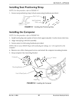
Page 65 highlights
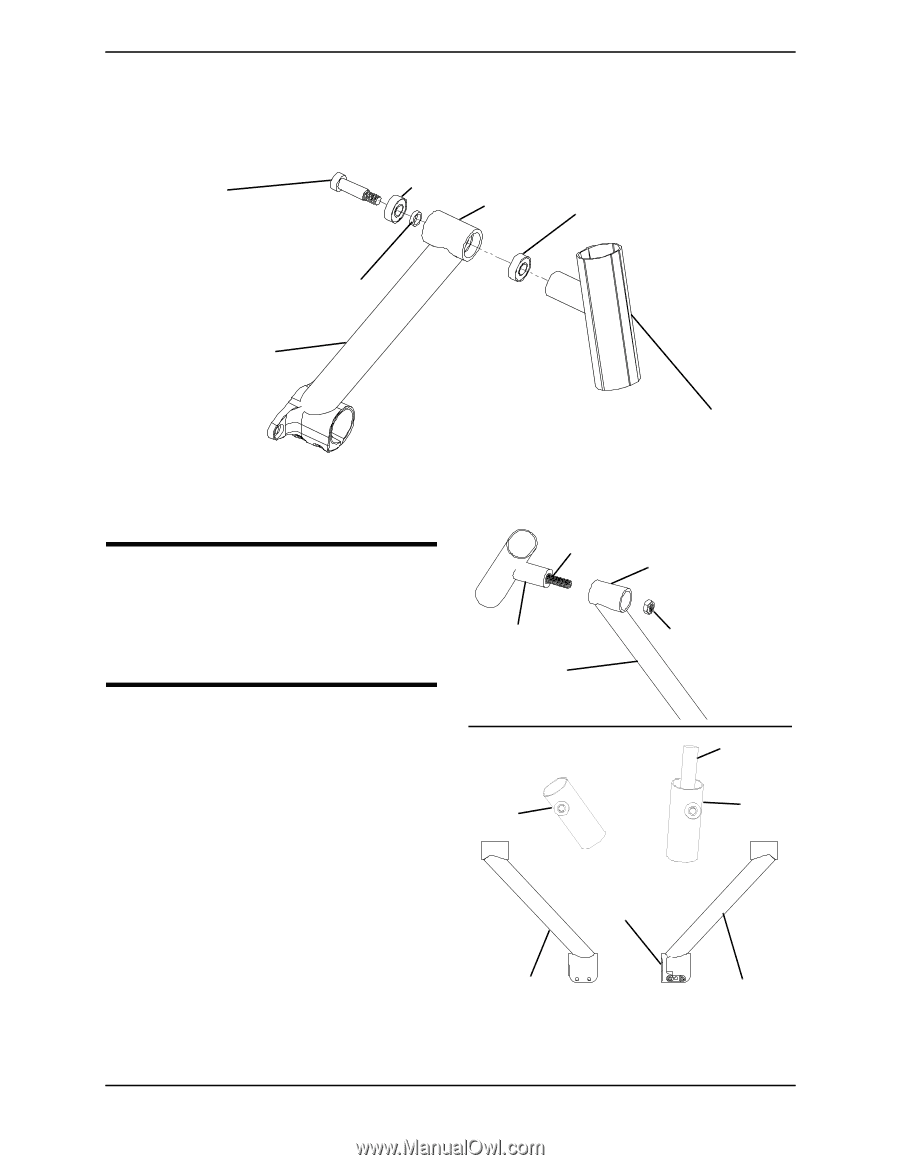
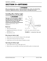
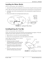
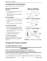
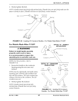
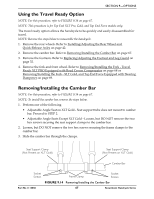
SECTION 9-OPTIONS 2. Firmly tighten the bolt. NOTE: Handle should spin freely with minimal play. If handle does not spin freely make sure the spacer is firmly in place. If handle still does not spin freely, contact Invacare. Bolt Bearing Crankarm Housing Bearing Spacer Crankarm Handle FIGURE 9.10 Installing V/S Crankarm Handles - For Models Made Before 7/12/07 For Models Made After 7/12/07 ƽ WARNING Failure to install handle assembly properly could result in injury. It is recommended to inspect this assembly prior to and after each use. Set Screw DETAIL "A" - HANDLE REPLACEMENT Crankarm Housing Handle Crankarm Locknut NOTE: For this procedure, refer to FIGURE 9.11. 1. Secure the handle to the crankarm housing using the set screw and locknut. NOTE: Use the right handle, the handle with a mounting post, with the right crankarm and left with left crankarm. The right crankarm has a flange at the base of the crankarm. The left crankarm does not. 2. Firmly tighten the locknut. NOTE: Handle should spin freely with minimal play. If handle does not spin freely, contact Invacare. DETAIL "B" - CRANKARM ORIENTATION Left Handle Mounting Post Right Handle Flange Left Crankarm Right Crankarm FIGURE 9.11 Installing V/S Crankarm Handles - For Models Made After 7/12/07 Part No 1114850 65 Recumbent Handcycle Series
-
 1
1 -
2
-
3
-
4
-
5
-
6
-
7
-
8
-
9
-
10
-
11
-
12
-
13
-
14
-
15
-
16
-
17
-
18
-
19
-
20
-
21
-
22
-
23
-
24
-
25
-
26
-
27
-
28
-
29
-
30
-
31
-
32
-
33
-
34
-
35
-
36
-
37
-
38
-
39
-
40
-
41
-
42
-
43
-
44
-
45
-
46
-
47
-
48
-
49
-
50
-
51
-
52
-
53
-
54
-
55
-
56
-
57
-
58
-
59
-
 60
60 -
 61
61 -
 62
62 -
 63
63 -
 64
64 -
 65
65 -
 66
66 -
 67
67 -
 68
68 -
 69
69 -
 70
70 -
71
-
72
-
73
-
74
-
75
-
76
 |
 |