Invacare XLTPRO Owners Manual - Page 67
Using the Travel Ready Option, Removing/Installing the Camber Bar
 |
View all Invacare XLTPRO manuals
Add to My Manuals
Save this manual to your list of manuals |
Page 67 highlights
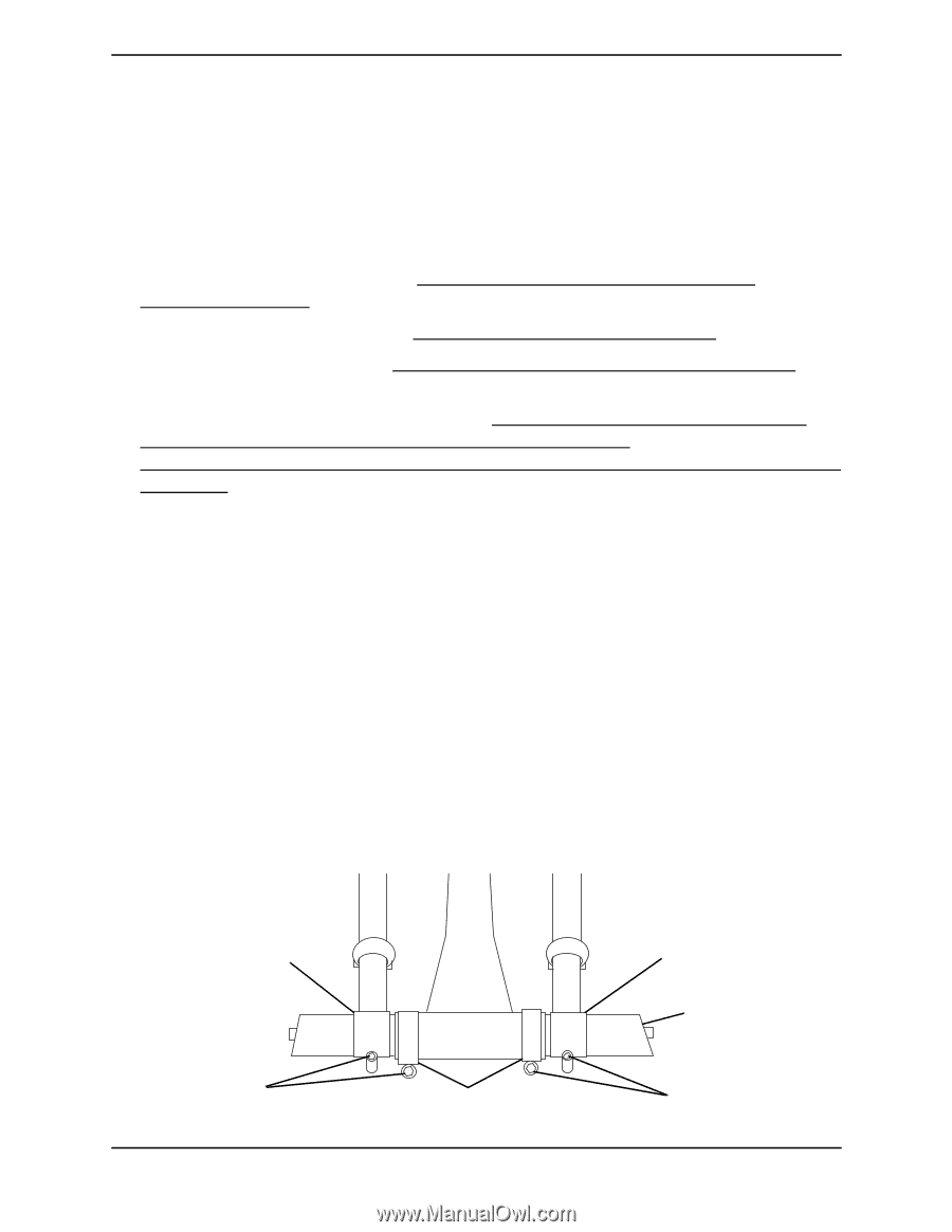
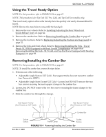
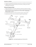
SECTION 9-OPTIONS Using the Travel Ready Option NOTE: For this procedure, refer to FIGURE 9.14 on page 67. NOTE: This procedure is for Top End XLT Pro, Gold, and Top End Force models only. The travel ready option allows the handcycle to be quickly and easily disassembled for travel. NOTE: Reverse the steps below to reassemble the handcycle. 1. Remove the rear wheels. Refer to Installing/Adjusting the Rear Wheel and Quick‐Release Axles on page 42. 2. Remove the camber bar. Refer to Removing/Installing the Camber Bar on page 67. 3. Remove the footrests. Refer to Replacing/Adjusting the Footrest and Leg Guard on page 32. 4. Remove the fork and front wheel. Refer to Removing/Installing the Fork ‐ Travel Ready XLT PRO Equipped with Road Crown Compensator on page 68 or Removing/Installing the Fork ‐ XLT Gold, and Top End Force Equipped with Steering Dampener on page 69. Removing/Installing the Camber Bar NOTE: For this procedure, refer to FIGURE 9.14 on page 67. NOTE: To install the camber bar, reverse the steps below. 1. Perform one of the following • Adjustable Angle Seat on XLT Gold ‐ Seat support tube does not mount to camber bar. Proceed to STEP 2. • Adjustable Angle Seats Except XLT Gold ‐ Loosen, but DO NOT remove the two hex screws securing the seat support clamps to the camber bar. 2. Loosen, but DO NOT remove the two hex screws securing the frame clamps to the camber bar. 3. Slide the camber bar through the clamps. Seat Support Clamp (Not Present on XLT Gold) Seat Support Clamp (Not Present on XLT Gold) Camber Bar Socket Screws Frame Clamp Socket Screws FIGURE 9.14 Removing/Installing the Camber Bar Part No 1114850 67 Recumbent Handcycle Series
-
 1
1 -
2
-
3
-
4
-
5
-
6
-
7
-
8
-
9
-
10
-
11
-
12
-
13
-
14
-
15
-
16
-
17
-
18
-
19
-
20
-
21
-
22
-
23
-
24
-
25
-
26
-
27
-
28
-
29
-
30
-
31
-
32
-
33
-
34
-
35
-
36
-
37
-
38
-
39
-
40
-
41
-
42
-
43
-
44
-
45
-
46
-
47
-
48
-
49
-
50
-
51
-
52
-
53
-
54
-
55
-
56
-
57
-
58
-
59
-
60
-
61
-
 62
62 -
 63
63 -
 64
64 -
 65
65 -
 66
66 -
 67
67 -
 68
68 -
 69
69 -
 70
70 -
 71
71 -
 72
72 -
73
-
74
-
75
-
76
 |
 |