JVC HD 52Z575 Instructions - Page 10
Quick Setup, TV Models - service manual
 |
UPC - 046838013034
View all JVC HD 52Z575 manuals
Add to My Manuals
Save this manual to your list of manuals |
Page 10 highlights
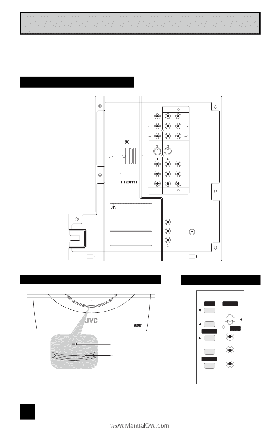
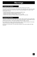
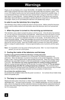
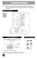
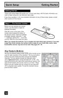
Quick Setup TV Models NOTE: Before you connect your television to another device, please refer to the proper diagrams for your specific TV and remote. These will help assist you in understanding how to connect your television to another device, as well as use the remote to set up your television. Rear Panel Diagram MODELS: HD-61Z585 HD-52Z585 HD-61Z575 HD-52Z575 CENTER CHANNEL INPUT INPUT-2 Y VIDEO AV COMPULINK III VIDEO (DIGITAL) AUDIO (DIGITAL) DIGITAL IN L AUDIO R S-VIDEO Pb Pr S-VIDEO L AUDIO R OVER VIDEO L I AUDIO I R OVER Y VIDEO L Pb I AUDIO I R Pr INPUT-3 INPUT-1 UNPLUG THE POWER CORD FROM AC OUTLET BEFORE REMOVING THE REAR COVER When the rear cover is removed, follow "CAUTION AT DISASSEMBLY" procedure in the service manual before plugging the TV's power cord into an AC outlet. Failure to follow the procedure will result in PERMANENT damage to some of the television features. DÉBRANCHEZ LE CORDON DE LA PRISE DE COURANT C. A. AVANT DE RETIRER LE COUVERCLE ARRIÈRE. Une fois le couvercle arrière déposé suivez l procédure « ATTENTION LORS DU DÉMONTAGE » décrite dans une prise c.a. L'omission de suivre la procédure causera des dommages PERMANENTS à certaines fonctions du téléviseur. Licensed from BBE Sound, Inc. under USP4638258, 4482866 and 5510752. BBE is a registered trademark of BBE Sound, Inc. Sous licence de BBE Sound, Inc. BBE est une marque de fabrique déposée de BBE Sound, Inc. Autorizado con licencia de BBE Sound, Inc. BBE es une marca comercial registrada de BBE Sound, Inc. SUBWOOFER OUT L AUDIO OUTPUT R 75Ω (VHF/UHF) Front Panel Diagram Side Panel Diagram LAMP POWER LAMP POWER LAMP LED POWER LED • For information on the LED, see page 72. MODELS: HD-61Z585, HD-52Z585, HD-61Z575, HD-52Z575 10 MENU OPERATE + CHANNEL - INPUT 4 S-VIDEO OVER VIDEO + VOLUME - L/MONO R AUDIO
-
 1
1 -
2
-
3
-
4
-
 5
5 -
 6
6 -
 7
7 -
 8
8 -
 9
9 -
 10
10 -
 11
11 -
 12
12 -
 13
13 -
 14
14 -
 15
15 -
16
-
17
-
18
-
19
-
20
-
21
-
22
-
23
-
24
-
25
-
26
-
27
-
28
-
29
-
30
-
31
-
32
-
33
-
34
-
35
-
36
-
37
-
38
-
39
-
40
-
41
-
42
-
43
-
44
-
45
-
46
-
47
-
48
-
49
-
50
-
51
-
52
-
53
-
54
-
55
-
56
-
57
-
58
-
59
-
60
-
61
-
62
-
63
-
64
-
65
-
66
-
67
-
68
-
69
-
70
-
71
-
72
-
73
-
74
-
75
-
76
-
77
-
78
-
79
-
80
 |
 |