JVC RMP-2580U RM-P2580 Dome Controller Instructions (1148KB) - Page 11
JVC RMP-2580U - Remote Controller For Color Domes Manual
 |
View all JVC RMP-2580U manuals
Add to My Manuals
Save this manual to your list of manuals |
Page 11 highlights
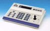
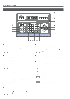
2. BASIC OPERATIONS POSITION SELECTION Selecting a Desired Preset Position ( REF. : Page 27 for the position presetting.) 1. 2. CAMERA display POSITION display REMOTE CONTROL UNIT RM-P2580 CAMERA POSITION Press the POSITION button so that the indicator lights up. Input the position number using the numeric keys (0 to 9). The input figure is shown in the POSITION display together with a period after it. (Example: When "48" is input) To clear the input figure, press the CLEAR button. POSITION POWER POWER ALARM KEY LOCK AUTO F-1 F-2 F-3 CAMERA/POSITION PAN/TILT POSITION POSITION button 1 4 7 CLEAR 2 5 8 0 /HOME 3 6 9 ENTER CAMERA OPTION 1 OPTION 2 AUTO PAN AUTO PATROL Numeric key buttons Period 3. CLEAR button - button + button Press the ENTER button to enter the input position number. The video of the selected position will be output from the MONITOR OUTPUT connectors on the rear panel. At this time, the period in the POSITION display disappears. NOTE When a position number that has not been preset is selected, the POSITION display shows the selected position number but the video is not switched to that position. ENTER button 4. To view the video of the next recorded position number, press the + button. To view the video of the previous recorded position number, press the - button. NOTE When TK-C675B cameras are used, make sure that the lower 4 digits inscribed on the serial number on their rear panels are as shown below. Otherwise the cameras cannot be moved to the desired positions. TK-C675BU: #0060 or after When the serial number of a camera is other than the above, please consult your nearest JVC-authorized service agent. Setting All Cameras to the Home Positions ( CAMERA display POSITION display REF. : Page 27 for the home position presetting.) 1. 2. F-3 Press the CAMERA button so that the indicator lights up. Press the HOME button. The CAMERA display shows "A" and POSITION display shows "H0". CAMERA POSITION REMOTE CONTROL UNIT RM-P2580 CAMERA POWER POWER ALARM KEY LOCK AUTO F-1 F-2 POSITION CAMERA/POSITION PAN/TILT POSITION CAMERA button 1 4 7 CLEAR 2 5 8 0 /HOME 3 6 9 ENTER CAMERA 3. Press the ENTER button to move all the cameras into their home positions. When the cameras have moved to the home positions, the CAMERA display shows the camera number that was selected before the HOME button was pressed. OPTION 1 OPTION 2 AUTO PAN AUTO PATROL HOME button 11
-
 1
1 -
2
-
3
-
4
-
5
-
 6
6 -
 7
7 -
 8
8 -
 9
9 -
 10
10 -
 11
11 -
 12
12 -
 13
13 -
 14
14 -
 15
15 -
 16
16 -
17
-
18
-
19
-
20
-
21
-
22
-
23
-
24
-
25
-
26
-
27
-
28
-
29
-
30
-
31
-
32
 |
 |
