JVC RMP-2580U RM-P2580 Dome Controller Instructions (1148KB) - Page 13
JVC RMP-2580U - Remote Controller For Color Domes Manual
 |
View all JVC RMP-2580U manuals
Add to My Manuals
Save this manual to your list of manuals |
Page 13 highlights
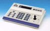
2. BASIC OPERATIONS AUTO SEQUENCE OPERATION Operation with the Basic System ( REF. : Page 32 for the switching interval setting.) When the AUTO button is pressed, the AUTO indicator lights up and the MONITOR OUTPUT connectors output the camera images, switching them in order of camera numbers at constant intervals. (Example) When using cameras 1 to 6 Camera 1 Camera 2 Camera 3 Camera 6 Camera 5 Camera 4 Lights up. AUTO button REMOTE CONTROL UNIT RM-P2580 CAMERA POWER POWER SET ALARM KEY LOCK AUTO F-1 F-2 F-3 POSITION 1. SETUP MENU CAMERA display POSITION display Press the AUTO button. The LED indicator lights up and the AUTO SEQUENCE operation starts. The CAMERA display shows the camera number of the video being output from the MONITOR OUTPUT 1 connector. The POSITION display shows the camera operation details. ( REF. : Page 10) NOTES ● During the AUTO SEQUENCE operation, the camera selection, manual selection, AUTO PAN operation and AUTO PATROL operation are not available. ● When the auto mode AUTO SEQUENCE operation is switched from ON to OFF, the MONITOR OUTPUT connectors output the video at the moment of the ON-OFF switching. ● In the case of Applied System (B Mode), the video from the MONITOR OUTPUT is displayed in either auto sequence or in multi-split screen depending on the setting of the connected frame switcher. 2. To stop the AUTO SEQUENCE operation, press the AUTO button once again. 13
-
 1
1 -
2
-
3
-
4
-
5
-
6
-
7
-
 8
8 -
 9
9 -
 10
10 -
 11
11 -
 12
12 -
 13
13 -
 14
14 -
 15
15 -
 16
16 -
 17
17 -
 18
18 -
19
-
20
-
21
-
22
-
23
-
24
-
25
-
26
-
27
-
28
-
29
-
30
-
31
-
32
 |
 |
