Jensen JGC9536ADB Installation Manual - Page 4
Caution - knobs
 |
UPC - 719881123813
View all Jensen JGC9536ADB manuals
Add to My Manuals
Save this manual to your list of manuals |
Page 4 highlights
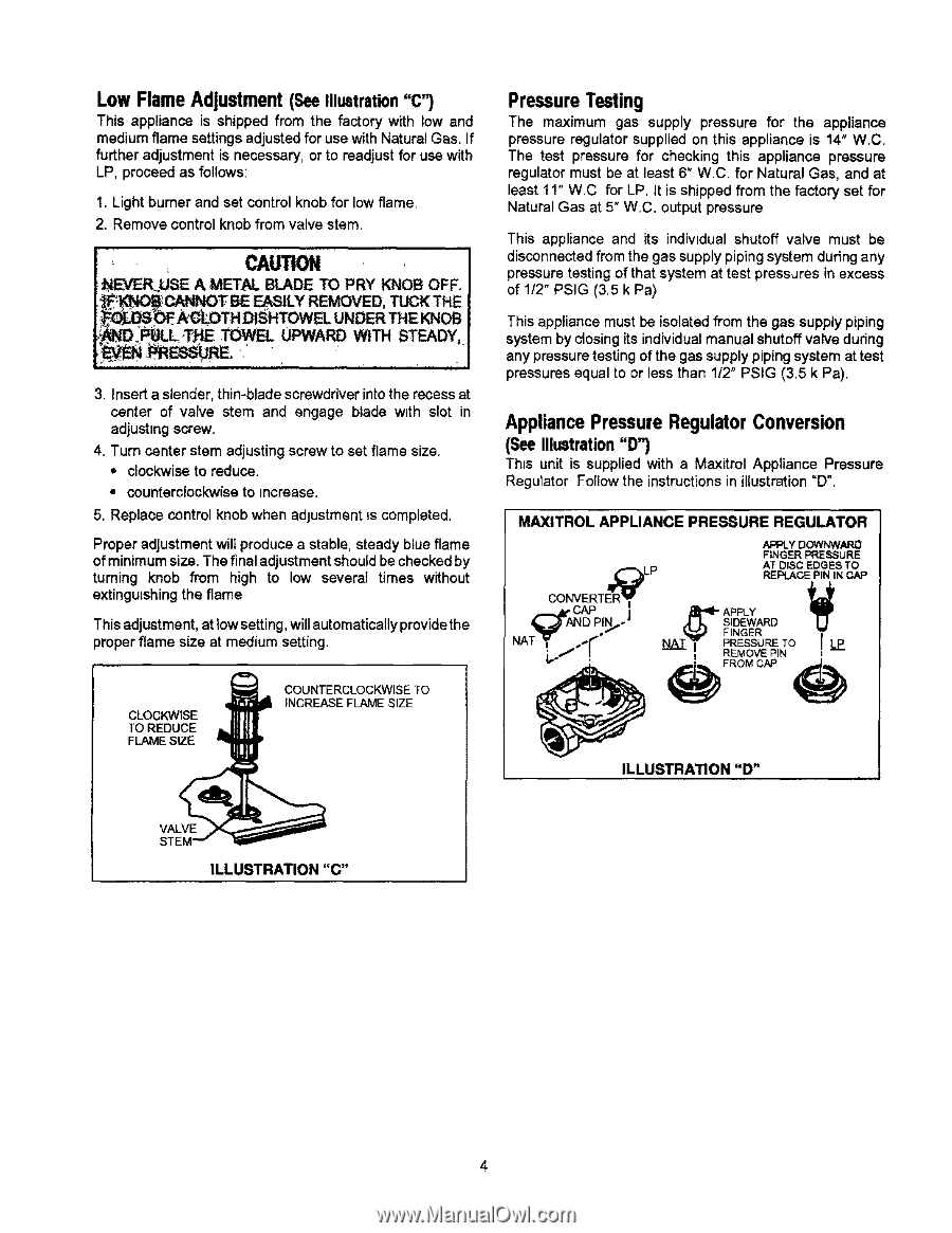
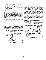
Low Flame Adjustment (SeeIllustration"C") This appliance is shipped from the factory with low and mediumflame settingsadjusted for use with Natural Gas. If further adjustment is necessary, or to readjust for use with LP, proceed as follows: 1. Light burner and set control knob for low flame. 2. Remove control knob from valve stem. , CAUTION _EVER_USE A METAL BLADE TO PRY KNOB OFF. LE_"CAN_DT BE EASILY REMOVED, TUCK THE _FA_ -CL- OTH DISHTOWEL UNDER THE,KNOB _D._LoTHE TOWEL UPWARD WITH STEADY, i i i i i '11 i i i ii ,,, " i ' if 3. Insert a slender, thin-bladescrewdriver into the recess at center of valve stem and engage blade w_th slot in adjusting screw. 4. Turn center stem adjusting screw to set flame size. • clockwise to reduce. • counterclockwise to increase. 5, Replace control knob when adjustment is completed. Proper adjustmentwill produce a stable, steady blue flame of minimum size. The final adjustmentshould be checked by turning knob from high to low several times without extinguishing the flame This adjustment, at low setting, will automatically provide the proper flame size at medium setting. PressureTesting The maximum gas supply pressure for the appliance pressure regulator supplied on this appliance is 14" W.C. The test pressure for checking this appliance pressure regulator must be at least 6" W.C. for Natural Gas, and at least 11" W.C for LP. It is shipped from the factory set for Natural Gas at 5" W.C. output pressure This appliance and its individual shutoff valve must be disconnected from the gas supply piping system during any pressure testing of that system at test pressures in excess of 112"PSIG (3.5 k Pa) This appliance must be isolated from the gas supply piping system by closingits individual manual shutoffvalve during any pressuretesting of the gas supply piping system at test pressures equal to or less than 112"PSIG (3.5 k Pa). Appliance Pressure Regulator Conversion (See Illustration"D") This unit is supplied with a Maxitrol Appliance Pressure Regulator Follow the instructions in illustration=D". MAXITROL APPLIANCE PRESSURE REGULATOR APPLY DOWhhNARD FINGER PRESSURE N.A,_"AN D PJN._'" N AT_I'- !ilEG_EWR_RTEO CLOCKWISE TO REDUCE FLAME SIZE COUNTERCLOCKWISE TO INCREASE FLAME SIZE ILLUSTRATION "D" VALVE ILLUSTRATION "C"
-
 1
1 -
 2
2 -
 3
3 -
 4
4 -
 5
5 -
 6
6 -
 7
7 -
 8
8
 |
 |