Jensen MPX6411 Instruction Manual - Page 7
Wiring with a Wiring, Adapter Purchased, Separately - wiring harnesses
 |
UPC - 043258302700
View all Jensen MPX6411 manuals
Add to My Manuals
Save this manual to your list of manuals |
Page 7 highlights
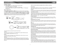
MPX6411 WIRING Wiring with a Wiring Adapter (Purchased Separately) Connect Wires You can make all these connections without even being in the vehicle. 1. Splice or crimp wires. 2. Attach wiring adapter to the car wiring harness. Wiring Diagram / Color Codes 1. Power Antenna (dark blue wire) - Connect to the power antenna or a amplifier. If not used, tape the bare end of wire. 2. Ground (black wire) Connect to the ground terminal or a clean, unpainted part of the chassis. 3. Memory/Battery (yellow wire) - Connect to the battery or to a 12 volt power source that is always alive. The radio will not work if this wire is not connected. 4. Accessory/Ignition (red wire) - Connect to the existing radio wire or radio fuse. 5. Left front speaker 6. Right front speaker 7. Left rear spearker 8. Right rear speaker 9. RCA Outputs to Amplifier 10. Auxiliary Input Cable (yellow) 11. Antenna 12. XM® Direct Connect Cable 13. XM® Audio Input (black RCA) 14. Subwoofer Output (blue) 15. CD Changer/JPORT connector - Use this 8-pin DIN socket to connect an optional CD Changer or JPORT (sold separately). *TERK XMDJEN100 cables sold separately. **TERK XMD1000 Direct Tuner and antenna sold separately. NOTE: The amplifier in this radio is only designed for use with four speakers. Never combine (bridge) outputs for use with two speakers. Never ground negative speaker leads to chassis ground. Failure to wire exactly as shown may cause electrical damage to the radio. 3
-
 1
1 -
 2
2 -
 3
3 -
 4
4 -
 5
5 -
 6
6 -
 7
7 -
 8
8 -
 9
9 -
 10
10 -
 11
11 -
 12
12 -
13
-
14
-
15
-
16
-
17
-
18
-
19
-
20
-
21
-
22
-
23
-
24
-
25
-
26
-
27
-
28
-
29
-
30
-
31
-
32
-
33
-
34
-
35
-
36
-
37
-
38
-
39
-
40
-
41
-
42
-
43
-
44
-
45
-
46
-
47
-
48
-
49
-
50
-
51
-
52
-
53
-
54
-
55
-
56
-
57
-
58
 |
 |
