Kenmore 33124 Owners Manual - Page 9

Temperature-Pressure, Relief Valve

Page 9 highlights

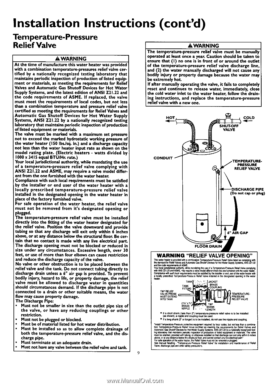
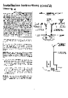
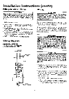
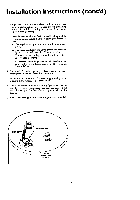
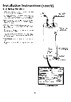
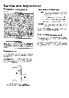
Installation Instructions (cont'd) Temperature-Pressure Relief Valve AWARNING AWARNING I At the time of manufacture this water heater was provided with a combinationtemperature-pressures relief valve cer- tified by a nationally recognized testing laboratory that maintains periodic inspectionof production of listedequipment or materials, as meeting the requirements for Relief Valves and Automatic Gas Shutoff Devicesfor Hot Water SupplySystems,and the latest edition of ANSI Z21.22 and the code requirements of ASME. If replaced, the valve must meet the requirements of local codes, but not less than a combination temperature and pressurerelief valve certified as meeting the requirements for Relief Valvesand Automatic Gas Shutoff Devices for Hot Water Supply Systems, ANSI Z21.22 by a nationally recognized testing laboratory that maintains periodic inspectionof production of listedequipment or materials. The valve must be marked with a maximum set pressure The temperature-pressure relief valve must be manually operated at least once a year. Caution should be taken to ensure that (I) no one is in front of or around the outlet of the temperature-pressure relief valve discharge line, and (2) the water manually dischargedwill not cause any bodily injury or property damage because the water may be extremely hot. If after manually operating the valve, it fails to completely reset and continues to release water, immediately, close the cold water inlet to the water heater, follow the draining instructions, and replace the temperature-pressure relief valve with a new one. SHUTOFF VALVE not to exceed the marked hydrostaticworking pressureof the water heater (150 Ibs./sq.in.) and a dischargecapacity not lessthan the water heater input rate as shownon the model rating plate. (Electric heaters - watts divided by 1000x 3415 equal BTU/Hr. rate.) Your localjurisdictional authority, while mandatingthe use of a temperature-pressure relief valve complying with ANSI Z21.22 and ASME, may require a valve model different from the one furnishedwith the water heater. PRESSURE RELIEF VALVE Compliance with suchlocal requirements must be satisfied by the installer or end user of the water heater with a locally prescribed temperature-pressure relief valve installed in the designatedopening in the water heater in place of the factory furnishedvalve. For safe operation of the water heater, the relief valve must not be removed from it's designated opening or plugged. The temperature-pressure relief valve must be installed directly into the fitting of the water heater designatedfor PIPE (Do not cap or plug) the relief valve. Positionthe valve downward and provide tubing so that any dischargewill exit only within 6 inches above,or at any distancebelow the structural floor. Be cer- 6" AIR GAP tain that no contact is made with any live electrical part. The dischargeopening must not be blocked or reduced in size under any circumstances. Excessivelength, over 30 feet, or useof more than four elbowscan causerestriction and reducethe dischargecapacityof the valve. No valve or other obstruction is to be placed between the relief valve and the tank. Do not connecttubing directly to dischargedrain unlessa 6" air gap is provided.To prevent bodily injury, hazard to life, or property damage,the relief valve must be allowed to discharge water in quantities should circumstancesdemand. If the dischargepipe is not connected to a drain or other suitable means, the water flow may causeproperty damage. The DischargePipe: Must not be smaller in size than the outlet pipe size of the valve, or have any reducing couplings or other restriction. Must not be pluggedor blocked. Must be of material listedfor hot water distribution. Must be installed so as to allow complete drainage of both the temperature-pressure relief valve, and the dischargepipe. Must terminate at an adequatedrain. Must not haveany valvebetween the raliefvalveand tank. WARNING "RELIEF VALVE OPENING" _*ls w_er I'_ater=sprov_edwr_haco_'_na'_ Terrgeheure.PressurRee_ Valvelisted_ w_h Ihe star_ardforRal_ Valvesa.':dAUfo_bC Gas Shuto_[_,_es forHotWalerSupply_sC,_l _ Ycurkx:ajJu'unsdc'Joraul lhe_, v_le rnar_0ng Iheuseof aTer'_perature.Ppz_surRedaefVahe coming withANSZ2122 andASME,r_layrequirea valvemcdel dilterenItrom theoPefomishedwr_thewate_heater a lOCallypreservedTemperatare.Pr_ssuRreel_ Valve inste_edin the deS

  • 1
  • 2
  • 3
  • 4
  • 5
  • 6
  • 7
  • 8
  • 9
  • 10
  • 11
  • 12
  • 13
  • 14
  • 15
  • 16
  • 17
  • 18
  • 19
  • 20
  • 21
  • 22
  • 23
  • 24

Installation
Instructions
(cont'd)
Temperature-Pressure
Relief Valve
AWARNING
I
At the time of
manufacture
this water heater was provided
with a combinationtemperature-pressures
relief
valve cer-
tified by a nationally
recognized
testing laboratory that
maintains periodic inspectionof production of listed
equip-
ment or materials, as meeting the
requirements
for Relief
Valves and Automatic Gas Shutoff Devicesfor Hot Water
SupplySystems,and the latest
edition
of ANSI Z21.22 and
the code
requirements
of ASME. If replaced, the valve
must meet the requirements of local codes, but not less
than a combination temperature and pressurerelief valve
certified as meeting the
requirements
for Relief Valves
and
Automatic
Gas Shutoff Devices for Hot Water
Supply
Systems, ANSI Z21.22 by a nationally
recognized
testing
laboratory that maintainsperiodicinspectionof production
of listedequipment or materials.
The
valve must be marked with a maximum set pressure
not
to
exceed
the marked hydrostaticworking pressureof
the water heater (150 Ibs./sq.in.)
and
a dischargecapacity
not lessthan the water heater input rate as
shown
on the
model
rating
plate. (Electric
heaters
- watts divided by
1000x 3415 equal BTU/Hr. rate.)
Your localjurisdictional
authority,
while
mandatingthe use
of
a
temperature-pressure
relief
valve complying with
ANSI Z21.22 and ASME, may
require
a valve model differ-
ent
from the one furnishedwith the water heater.
Compliance with suchlocal
requirements
must be satisfied
by the installer or
end
user of the water heater with a
locally prescribed
temperature-pressure
relief
valve
installed in the designatedopening in the water heater in
place of the factory furnishedvalve.
For safe operation of the water heater, the relief valve
must not be
removed
from it's designated opening or
plugged.
The
temperature-pressure relief valve must be installed
directly into the fitting of the
water
heater designatedfor
the
relief
valve. Positionthe valve downward
and
provide
tubing so
that
any dischargewill
exit
only within 6 inches
above,or at
any
distancebelow the structural floor. Be cer-
tain
that no contact is made with
any
live
electrical
part.
The dischargeopening must
not
be blocked or
reduced
in
size under any circumstances. Excessivelength, over 30
feet, or useof more than four
elbows
can cause
restriction
and reducethe dischargecapacityof the valve.
No valve or other obstruction is to be placed between the
relief
valve and the tank. Do
not
connecttubing directly to
dischargedrain unlessa 6" air gap is provided.To prevent
bodily injury, hazard to life, or property damage,the relief
valve must be allowed to discharge water in quantities
should circumstancesdemand. If the dischargepipe is
not
connected to a drain or other suitable means, the water
flow may causeproperty damage.
The DischargePipe:
Must
not
be smaller in size than the outlet pipe size of
the valve, or
have
any reducing couplings or other
restriction.
Must not be pluggedor blocked.
Must be of material listedfor hot water distribution.
Must be installed so as to allow complete drainage of
both the temperature-pressure
relief
valve, and the dis-
chargepipe.
Must terminate at an adequatedrain.
Must not have
any
valvebetweenthe raliefvalveandtank.
AWARNING
The temperature-pressure relief valve must be manually
operated at least once a year. Caution should be
taken
to
ensure
that (I)
no
one is in front of or around the outlet
of the temperature-pressure
relief valve discharge line,
and
(2) the water manually dischargedwill not cause any
bodily injury or property damage because the water may
be
extremely hot.
If after manually operating the valve, it fails to completely
reset
and continues to
release
water, immediately, close
the cold water inlet to the water heater, follow the drain-
ing instructions, and replace the temperature-pressure
relief
valve with a
new
one.
SHUTOFF
VALVE
PRESSURE
RELIEF
VALVE
PIPE
(Do not cap or plug)
6" AIR GAP
WARNING
"RELIEF
VALVE OPENING"
_*ls
w_er I'_ater
=s
prov_edwr_haco_'_na'_
Terrgeheure.Pressure
Re_
Valvelisted
_
w_h
Ihe star_ard
for
Ral_ Valvesa.':d
AUfo_bC
GasShuto_
[_,_es
for
HotWalerSupply
_sC,_l
_
Ycur
kx:aJ
ju'unsdc'Joral
aulhe_, v_le rnar_0ng Iheuseof a
Ter'_perature.Ppz_sure
RdaefVahe
coming
withANSZ2122andASME,r_layrequireavalve
mcdel
dilterent
Irom
theoPe
fomished
wr_
the
wate_heater
a
lOCally
preservedTemperatare.Pr_ssure
Rel_ Valveinste_edinthe deS<jnatedopeninginItm water
TANK
_._C_ET
TANK
BRASS
COUP1JNG
T&P RELIEF
VALVE PROBE
INTO TANK
l
TEMPERATURE-
PRESSURE
I
RELIEF VALVE
T&P
BRASS
_
SHANK
NIPPLE
''
LENGTH
If a short shank (tess tr_ul2") temper`Eture-prsssure
relief valve is to be installed
(as shown), a nip_
and couplingmust be used¸
If a longshank(2"
or
longer) is tobe
instalfod,
do
not
use the
nipp_ and
co_pling
nslall
Ten',peraturePressulepro_ect_ve
eq_prr_
rec_red
by
localcodes,butnotlesstl'ana cor_0Pa.
IO,
Tempera
ur_.PressurQ
Re
ef Vah/e
¢ert
I
ed as
meel
ng
the
requ remenls
or
Re
e
Vllves
,End
Autor_at=:
GasShutoff
_ces
forHo_-wa_er
,%pply
Systems,
ANSZ2122 bya
nalfoflally
recognized
lesl-
inglabomtc_tha_
ma_m_
peno_ inspec_ ofpmdu¢zono/kstedequipment
or matenalsThe val'_
muslbeo_e_led,pr0_Kted
_th
tub_, Orotherwise
installedso thatdm_zrgec_ exitonlyw_
6
_che$
above,or al
_
distancebelowlie
aln_ci_r_l
floor,andcannc_contact
any
ire electnodpad.'
Forsateop_atlc_C_thewaterheater,theRelle{V_lve
_
riotbe
remov_
or pfo
_ged
See
manualheading
- "Temperat_re-Pressur
e ReliefValve"forinstallationandrnainlenanceof
_elie_
Valve,d_;t,argerapea_ ot_ersatelypreca_c_s
9