Kenmore 33176 Owners Manual - Page 17
flame.Rinseoffsoapy
 |
View all Kenmore 33176 manuals
Add to My Manuals
Save this manual to your list of manuals |
Page 17 highlights
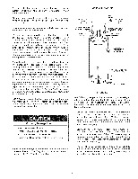
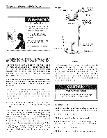
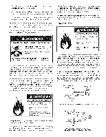
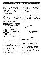
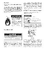
• Areadilayccessibmleanuaslhuot ffvalveinthegassupply lineservintghewatehr eatear,nd • A dripleg(sedimetrnatpa) heaodfthegascontroval lvetohelp prevednitrat ndforeigmnaterifarlosmenteritnhgegascontrvoal lve. • Aflexiblegasconnectoragrounjdointunionbetweetnhe shuot ffvalveandcontrovlalvetopermsitervicinogftheunit. inch (3.5 kPa). It shall be isolated from the gas supply piping system by closing its individual manual shut-off valve during any pressure testing of the gas supply piping system at test pressures equal to or less than 1/2 pound per square inch (3.5 kPa). Connecting the gas piping heater can be accomplished in Figures 20 and 21. to the gas control valve of the water by either of the two methods shown Besuretocheckallthegaspipingforleaksbeforelightintghe Sediment Traps watehr eaterU. sea soapwy atesr olutionn,ota matchoropen flame.Rinseoffsoapsyolutioanndwipedry. Theminimuminletgaspressursehownontheratingplateis thatwhichwillpermfitiringattheratedinput. Fire and Explosion Hazard Contaminants in gas lines can cause fire or explosion. Breathing Hazard - Carbon Monoxide Gas High altitude orifice must be installed for operations above 2,000 ft. (610 m). Contact a qualified installer or service agency. Breathing carbon monoxide can cause brain damage or death. Always read and understand instruction manual. If a standard model is installed above 2,000 feet (610 m) the input rating should be reduced at the rate of 4 percent for each 1,000 feet (305 m ) above sea level which requires replacement of the burner orifice in accordance with National Fuel Gas Code ANSI Z223.1/NFPA 54. Contact your local Sears Service Center or local gas supplier for further information. Failure to replace the standard orifice with a high altitude orifice when installed at elevations above 2,000 feet (610 m) could result in improper and inefficient operation of the appliance, producing carbon monoxide gas in excess of safe limits, which could result in serious injury or death. Contact your local Sears Service Center or local gas supplier for any specific changes which may be required in your area. Clean all gas piping before installation. ° Install drip leg in accordance with NFPA54. Contaminants in the gas lines may cause improper operation of the gas control valve that may result in fire or explosion. Before attaching the gas line be sure that all gas pipe is clean on the inside. To trap any dirt or foreign material in the gas supply line, a drip leg (sometimes called a sediment trap) must be incorporated in the piping. The drip leg must be readily accessible. Install in accordance with the Gas Piping section. Refer to the current edition of the National Fuel Gas Code, ANSI Z223.1/NFPA 54. A sediment trap shall be installed as close to the inlet of the water heater as practical at the time of water heater installation. The sediment trap shall be either a tee fitting with a capped nipple in the bottom outlet or other device recognized as an effective sediment trap. If a tee fitting is used, it shall be installed in conformance with one of the methods of installation, shown in Figures 20 and 21. GROuUN_JNOINT (OPTIONAL) GAS CONTROL Fire and Explosion Hazard • Use joint compound or tape com patible with propane. • Leak test before operating heater. • Disconnect gas piping and shut-off valve before pressure testing system. The appliance and its gas connection must be leak tested before placing the appliance in operation. The appliance and its individual shut-off valve shall be disconnected from the gas supply piping system during any pressure testing of that system at test pressures in excess of 1/2 pound per square 17 CAP FIGURE 20. GAS PIPING WITH FLEXIBLE CONNECTOR. UNION (OPTIONAL) BLACK PiPE GROUND JOINT (736",2 MmIN_)_ GAS CONTROL VALVE CAP FIGURE 21. GAS PiPiNG WITH ALL BLACK IRON PmPE TO GAS CONTROL.
-
 1
1 -
2
-
3
-
4
-
5
-
6
-
7
-
8
-
9
-
10
-
11
-
 12
12 -
 13
13 -
 14
14 -
 15
15 -
 16
16 -
 17
17 -
 18
18 -
 19
19 -
 20
20 -
 21
21 -
 22
22 -
23
-
24
-
25
-
26
-
27
-
28
 |
 |
