Kenmore 4102 Installation Instructions - Page 5
Electrical, Connection, Range - slide
 |
View all Kenmore 4102 manuals
Add to My Manuals
Save this manual to your list of manuals |
Page 5 highlights
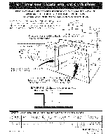
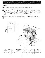
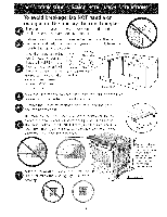
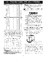
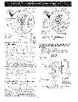
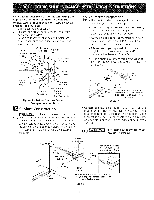
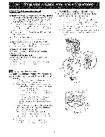
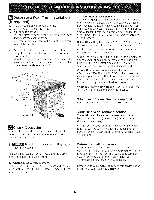
Appliance Rating Watts 120V / 208V 0-3120 3121-3900 3901-4160 4161-5200 5201-5570 5571-7430 7431-7800 7801-12500 12501-14500 Minimum L1 and L2 Conductors 16 Conductor Size, AWG Neutral Conductor Ground Conductor 16 14 16 16 12 14 16 12 14 16 10 12 16 10 12 14 10 12 12 10 10 12 10 8 12 10 Appliance Rating Watts 120V / 240V 0-3600 Minimum Conductor Size, AWG CLo1ndauncdtorLs2 16 CoNneduutcratol r 16 CGonroduunctdor 14 3601-4500 16 16 12 4501-4800 14 16 12 4801-6000 14 16 10 6001-6425 12 16 10 6426-8749 12 12 10 8750-14500 10 12 10 14501-16500 10 10 10 16501-24000 8 10 8 For mobile homes, new installations or recreational vehicles, use only a power supply kit designed for a range at 125V/250V 40A. Cord must have either 3 (when local code permits grounding through neutral) or 4 conductors. Terminal on end of wires must be either closed loop or open spade lug with upturned ends. Cord must have strain-releif clamp. See chart for the minimum wire size (general UL listing, local code may differ). Do not loosen the nuts which secure the factory-installed range wiring while connecting range. ElectricaJ eJectricaJ connection may occur. to terminaJ block faiJure or Joss of Electrical Connection to the Range appliance is manufactured with the neutral terminal connected to the frame. Electrical Shock Hazard * Electrical ground is required on this appliance. , Do not connect to the electrical suppJy until appliance is permanently grounded. , Disconnect power to the circuit breaker or fuse box before making the electrical connection. * This appliance must be connected to a grounded, metallic, permanent wiring system, or a grounding connector should be connected to the grounding terminal or wire lead on the appliance. Failure to do any of the above could result in a fire, personal injury or electrical shock. Three Conductor Wire Connection to Range If local codes permit connection of the frame grounding conductor to the neutral wire of the copper power supply cord (see Figure 3): I. Remove the 3 screws at the lower end of the rear wire cover, then bend the lower end of the rear wire cover (access cover) upward to expose range terminal connection block (see Figure 2). Range Connection Opening Size Chart Refer to chart below for proper range connection opening size and power supply cord kit ampere rating information. See serial plate on range for kilowatt rating data. See Serial Plate on Range for KW Rating 120/240 Volts 120/208 Volts Minimum Cord kit Ampere Rating Diameter (inches) of Range Connection Opening Cord Kit Direct Connection 8.8-16.5Kw 16.6-22.5Kw 7.9-12.5 Kw 40 Amp 12.6-18.5 Kw 50 Amp 1-3/8 in. 1-3/8 in. 1-1/8 in. 1-3/8 in. NOTE: Electric Slide-in Range is shipped from factory with I-I/8" dia. hole as shown on figure 3. If a larger hole is required, punch out the knockout. Risk of fire or electrical shock exists if an incorrect size range cord kit is used, the InstalJation Instructions are not foJJowed, or the strain reJief bracket is discarded. BEND REAR WIRE COVER HERE FOR ACCESS TO TERMINAL BLOCK Figure 2 2. Remove the 3 loose nuts (after you remove the rubber band) on the terminal block using 3/8" nut driver or socket. 3. Connect the neutral of the copper power supply cord to the center silver-colored terminal of the terminal block, and connect the other wires to the outer terminals. Match wires and terminals by color (red wires connected to the right terminal, black wires connected to the left terminal). 4. Replace the 3 nuts on the terminal block (see Figure 3). 5. Lower the terminal cover and replace the 3 screws.
-
 1
1 -
 2
2 -
 3
3 -
 4
4 -
 5
5 -
 6
6 -
 7
7 -
 8
8 -
 9
9 -
 10
10 -
 11
11 -
12
-
13
-
14
-
15
-
16
-
17
-
18
-
19
-
20
-
21
-
22
-
23
-
24
 |
 |
