Kenmore 60581 Use and Care Guide
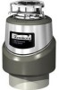
Kenmore 60581 - 3/4 HP Food Waste Disposer Manual
 |
View all Kenmore 60581 manuals
Add to My Manuals
Save this manual to your list of manuals |
Kenmore 60581 manual content summary:
- Kenmore 60581 | Use and Care Guide - Page 1
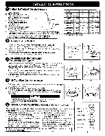
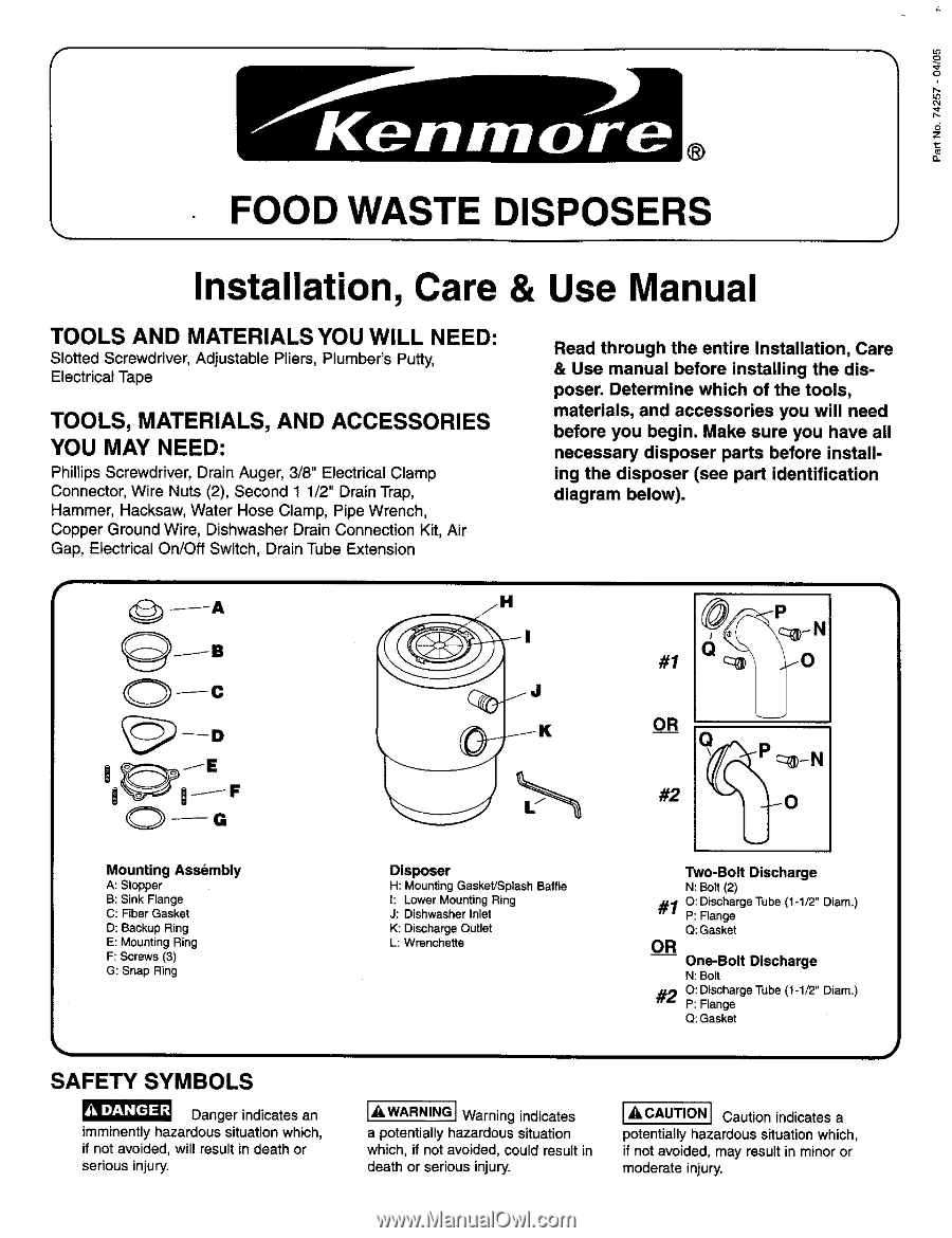
Use manual before installing the disposer. Determine which of the tools, materials, and accessories you will need before you begin. Make sure you have all necessary disposer parts before installing the disposer (see part identification diagram below). (_/A JlB O--c _ #1 OR @-N .-0 O--G Mounting - Kenmore 60581 | Use and Care Guide - Page 2
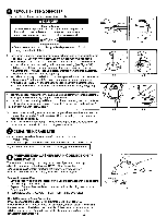
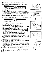
ring groove) may help hold parts in place while installing snap ring. (Remember to remove rubber band after snap ring is installed.) I sfkyipouahaeraedretpolaIcnisntgrucationnexis7t.ing disposer, go to Instruction 6. If this is a first time installation, SinkFlange FiberGasket _ O-- O BackupRing - Kenmore 60581 | Use and Care Guide - Page 3
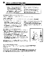
your head or body under disposer; unit could fall during removal or installation. 6-1 6-2 2. Disconnect drain trap from disposer waste discharge tube with adjustable pliers (see Fig. 6-1). (Also disconnect dishwasher drain connection, if required.) 3. Support disposer with one hand and insert - Kenmore 60581 | Use and Care Guide - Page 4
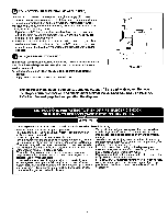
service panel until proper grounds are installed. There are two ways to connect electrical power to your disposer: 1.) Direct wire 2.) Plug in cord - installed at factory, or from Kenmore Kit #60686 (for all models listed in this manual) Disposer appliance. Grounding Instructions for Cord Connected - Kenmore 60581 | Use and Care Guide - Page 5
Property Damage Do not use thread sealants or pipe dope; they may harm the disposer and cause property damage. Two-Bolt DlechargeTube Installation (PreferredTwo-Bolt Installation) if replacing existing disposer, remove and discard existing discharge tube and gasket. (Unit will not seal properly with - Kenmore 60581 | Use and Care Guide - Page 6
installed disposer, containing important information in the event service is required. 1. Detach perforated portion of specification decal from lower portion of disposer. 2. Apply decal to disposer Read all instructions before using the appliance. This product is designed to dispose of normal - Kenmore 60581 | Use and Care Guide - Page 7
batch feed on/off switch is built into the disposer and activated by the stopper. (See Instruction 1,/nstal/ation Dimensions chart, for model reference.) 1. Read important safety instructions contained in the Installation, Care & Use manual. 2. Remove stopper from sink opening and place food waste - Kenmore 60581 | Use and Care Guide - Page 8
or workmanship which appear in this disposer. WARRANTY SERVICE IS AVAILABLE BY SIMPLY CONTACTING THE NEAREST SEARS SERVICE CENTER/DEPARTMENT IN THE UNITED STATES. This warranty applies only while this product is in use in the United States. This warranty gives you specific legal rights, and you
-
 1
1 -
 2
2 -
 3
3 -
 4
4 -
 5
5 -
 6
6 -
 7
7 -
8
 |
 |
f
®
FOOD WASTE
DISPOSERS
Installation,
Care & Use Manual
TOOLS
AND
MATERIALS
YOU WILL
NEED:
Slotted Screwdriver,
Adjustable
Pliers, Plumber's
Putty,
Electrical
Tape
TOOLS,
MATERIALS,
AND ACCESSORIES
YOU MAY NEED:
Phillips
Screwdriver,
Drain Auger, 3/8" Electrical
Clamp
Connector,
Wire Nuts (2), Second 1 1/2" Drain Trap,
Hammer,
Hacksaw, Water Hose Clamp,
Pipe Wrench,
Copper Ground Wire, Dishwasher
Drain Connection
Kit, Air
Gap, Electrical
On/Off Switch,
Drain Tube Extension
Read
through
the
entire
Installation,
Care
& Use
manual
before
installing
the
dis-
poser.
Determine
which
of the
tools,
materials,
and accessories
you will need
before
you
begin.
Make
sure
you
have
all
necessary
disposer
parts
before
install-
ing the
disposer
(see
part
identification
diagram
below).
(_/A
JlB
O--c
O--G
Mounting
Assembly
A: Stopper
B: Sink Flange
C: Fiber Gasket
D: Backup
Ring
E: Mounting Ring
F: Screws (3)
G: Snap
Ring
Disposer
H: Mounting
Gasket/Splash
Baffle
1: Lower Mounting Ring
J: Dishwasher Inlet
K:
Discharge
Outlet
L: Wrenchette
_
@-N
#1
.-0
OR
--#2
___N
Two-Bolt
Discharge
N:
Bolt
(2)
_10:
Discharge Tube (1-1/2"
Diam.)
P: Flange
Q:
Gasket
OR
One-Bolt
Discharge
N:
Bolt
#20:DischargeTube
(1-1/2" Diam.)
P: Flange
Q:
Gasket
SAFETY
SYMBOLS
Danger indicates
an
imminently
hazardous
situation
which,
if not avoided,
will result in death or
serious
injury.
I
t"
WARNINGI
Warning
indicates
a
potentially
hazardous
situation
which, if not avoided, could result in
death
or serious injury.
[_kCAUTION]
Caution
indicates a
potentially
hazardous
situation
which,
if not
avoided,
may result in minor or
moderate
injury,