Kenmore 60581 Use and Care Guide - Page 2
Disposer Width - parts
 |
View all Kenmore 60581 manuals
Add to My Manuals
Save this manual to your list of manuals |
Page 2 highlights
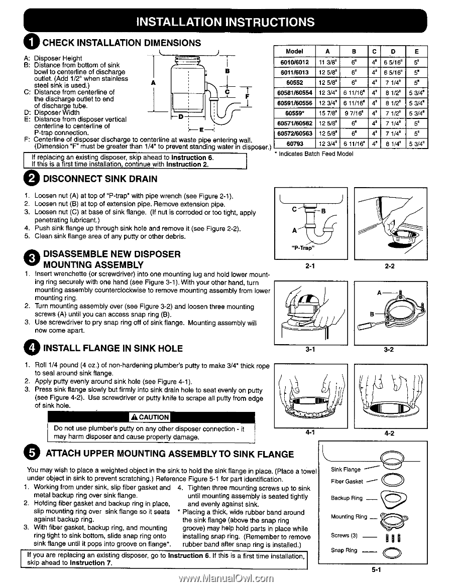
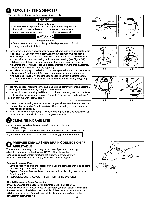
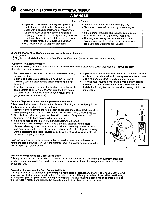
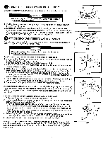
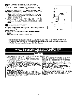
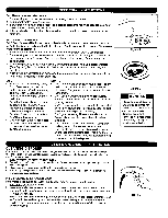
@) CHECK INSTALLATION DIMENSIONS A: Disposer Height B: Distance from bottom of sink bowl to centerline of discharge B outlet. (Add 1/2" when stainless steel sink is used.) C: Distance from centerline of the discharge outlet to end of discharge tube. D: Disposer Width E: Distance from disposer vertical centerline to centerline of P-trap connection. i ,',,--I__I F: Centerline of disposer discharge to centerline at waste pipe entering wall (Dimension "F" must be greater than 1/4" to prevent standing water in disposer.) i Iff trheisplaisciangfirasnt teimxiestiinngstadlliastpioons,er,cosnktiipnuaehewadithtoInsIntrsutcrtuiocntion2.6. II Model A B C 601016012 11 3/8" 6" 4' 6011/6013 12 5/8" 6" 4" 60552 12 5/80 6" 4" 60581/60554 12 3/4" 6 11/16 = 4" 60691/60556 12 3/4 = 6 1t/16 m 4" 60559* 15 7/8 = 9 7/16" 4" 60571/60562 12 5/8' 6" 4= 60572/60563 12 5/8" 6" 4' 60793 12 3/4" 6 11/16 = 4" • Indicates Batch Feed Model D 6 5/16" 6 5/16" 7 1/4" 8 1/2" 8 1/2" 7 1/2" 7 1/4" 7 1/4= 8 1/4" E 5" 5' 5_ 6 3/4 m 5 3/4' 5 3/4' 5" 5" 5 3/4" O DISCONNECT SINK DRAIN 1. Loosen nut (A) at top of "P-trap" with pipe wrench (see Figure 2-1). 9 2. Loosen nut (B) at top of extension pipe. Remove extension pipe. 3. Loosen nut (C) at base of sink flange. (If nut is corroded or too tight, apply penetrating lubricant,) 4. Push sink flange up through sink hole and remove it (see Figure 2-2). 5. Clean sink flange area of any putty or other debris. "P-Trap" O DMIOSUANSTSIENMGBLEASSENMEBWLYDISPOSER 2-1 1. insert wrenchette (or screwdriver) into one mounting lug and hold lower mount- ing ring securely with one hand (see Figure 3-1). With your other hand, turn mounting assembly counterclockwise to remove mounting assembly from lower mounting ring. 2, Turn mounting assembly over (see Figure 3-2) and loosen three mounting screws (A) until you can access snap ring (B). 3. Use screwdriver to pry snap ring off of sink flange. Mounting assembly will now come apart. / 2-2 O INSTALL FLANGE IN SINK HOLE 1. Roll 1/4 pound (4 oz.) of non-hardening plumber's putty to make 3/4" thick rope to seal around sink flange. 2. Apply putty evenly around sink hole (see Figure 4-1). 3. Press sink flange slowly but firmly into sink drain hole to seat evenly on putty (see Figure 4-2). Use screwdriver or putty knife to scrape all putty from edge of sink hole. 4-1 4-2 O ATTACH UPPER MOUNTING ASSEMBLYTO SINK FLANGE You may wish to place a weighted object in the sink to hold the sink flange in place. (Place a towel under object in sink to prevent scratching.) Reference Figure 5-1 for part identification. 1. Working from under sink, slip fiber gasket and metal backup ring over sink flange. 2. Holding fiber gasket and backup ring in place, slip mounting ring over sink flange so it seats against backup ring. 3. With fiber gasket, backup ring, and mounting ring tight to sink bottom, slide snap ring onto sink flange until it pops into groove on flange*. 4. Tighten three mounting screws up to sink until mounting assembly is seated tightly and evenly against sink. * Placing a thick, wide rubber band around the sink flange (above the snap ring groove) may help hold parts in place while installing snap ring. (Remember to remove rubber band after snap ring is installed.) I sfkyipouahaeraedretpolaIcnisntgrucationnexis7t.ing disposer, go to Instruction 6. If this is a first time installation, SinkFlange FiberGasket _ O-- O BackupRing -- _) MountingRing __ Screws(3)_ BiB SnapRing -- O 5-1
-
 1
1 -
 2
2 -
 3
3 -
 4
4 -
 5
5 -
 6
6 -
 7
7 -
 8
8
 |
 |