Kenmore 8804 Installation Instructions - Page 5
Location, Dryer - appliances
 |
View all Kenmore 8804 manuals
Add to My Manuals
Save this manual to your list of manuals |
Page 5 highlights
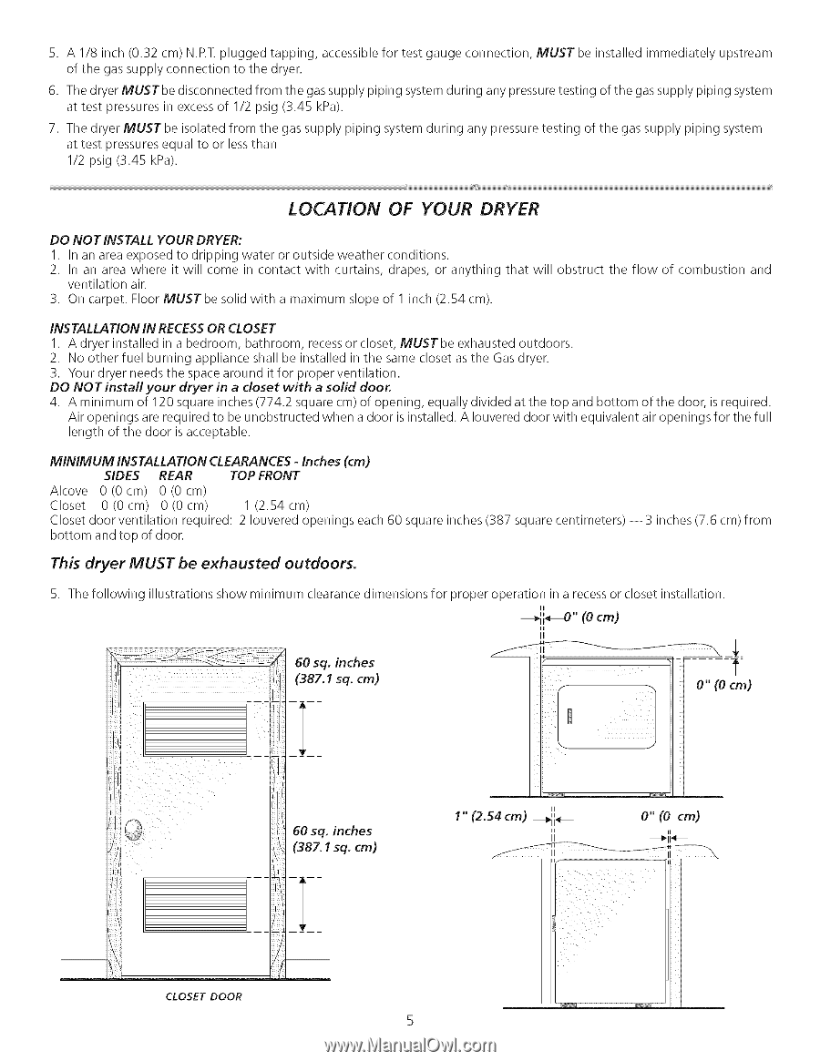
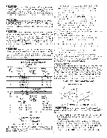
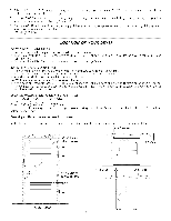
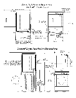
5. A 1/8 inch (0.32 cm) N.P.T.plugged tapping, accessible for test gauge connection, MUST be installed immediately upstream of the gas supply connection to the dryer. 6. The dryer MUST be disconnected from the gas supply piping system during any pressure testing of the gas supply piping system at test pressures in excess of 1/2 psig (3.45 kPa). 7. The dryer MUST be isolated from the gas supply piping system during any pressure testing of the gas supply piping system at test pressures equal to or less than 1/2 psig (3.45 kPa). LOCATION OF YOUR DRYER DO NOT INSTALL YOUR DRYER: I. In an area exposed to dripping water or outside weather conditions. 2. In an area where it will come in contact with curtains, drapes, or anything that will obstruct the flow of combustion and ventilation air. 3. On carpet. Floor MUSTbe solid with a maximum slope of I inch (2.54 cm). INSTALLATION IN RECESSOR CLOSET 1. A dryer installed in a bedroom, bathroom, recessor closet, MUSTbe exhausted outdoors. 2. No other fuel burning appliance shall be installed in the same closet as the Gas dryer. 3. Your dryer needs the space around it for proper ventilation. DO NOT install your dryer in a closet with a solid door. 4. A minimum of 120 square inches (774.2 square cm) of opening, equally divided at the top and bottom of the door, is required. Air openings are required to be unobstructed when a door is installed. A Iouvered door with equivalent air openings for the full length of the door is acceptable. MINIMUM INSTALLATION CLEARANCES - Inches (cm) SIDES REAR TOP FRONT Alcove 0(0cm) 0(0cm) Closet 0 (0 cm) 0 (0 cm) 1 (2.54 cm) Closet door ventilation required: 2 Iouvered openings each 60 square inches (387 square centimeters) -- 3 inches (7.6 cm) from bottom and top of door. This dryer MUST be exhausted outdoors. 5. The following illustrations show minimum clearance dimensions for proper operation in a recess or closet installation. II ---_ii_" (0 cm) li 0" (Ocm) II 1" (2.54 cm) _11,,_ II II o"(o cm) ii _11 _ CLOSET DOOR
-
 1
1 -
 2
2 -
 3
3 -
 4
4 -
 5
5 -
 6
6 -
 7
7 -
 8
8 -
 9
9 -
 10
10 -
 11
11 -
12
-
13
-
14
-
15
-
16
-
17
-
18
-
19
-
20
-
21
-
22
-
23
-
24
 |
 |